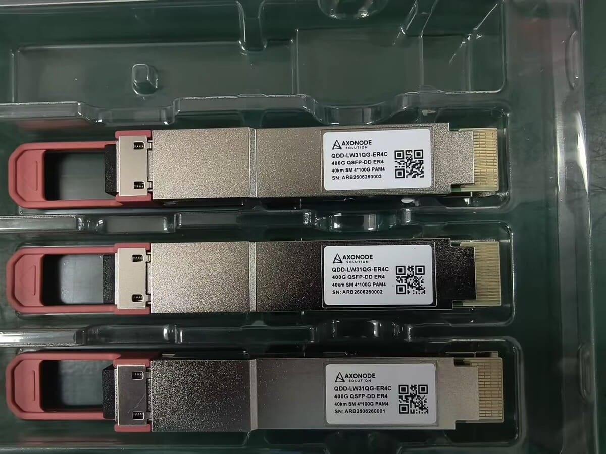
10G BiDi SFP+ 40km Guide: Pairing, Power Budget and Compatibility
Use this 10G BiDi SFP+ 40km guide to verify wavelength pairing, optical budget, receiver overload, switch compatibility and commissioning checks.

A “40 km” label does not make two 10G BiDi SFP+ modules a deployable pair. Engineers still need to confirm complementary transmit and receive wavelengths, the condition and loss of the single-fiber path, the optical power window at both ends, and whether each host accepts the module. Missing any one of these checks can leave a correctly rated link down or operating without enough margin. Validating these conditions before ordering can reduce wrong-module selection, unnecessary troubleshooting, deployment delays and avoidable replacement work.
This guide turns those risks into a practical selection and commissioning workflow. It helps you identify the correct pair, calculate usable optical margin, check receiver overload, gather host-compatibility information and prepare a controlled turn-up plan. The numerical values below are verified family-level technical references, not Axonode product specifications or a guarantee that every 40 km route will operate.
Before Ordering a 10G BiDi SFP+ 40km Pair, Check
- Confirm wavelength pairing. Each endpoint’s transmit wavelength must match the remote endpoint’s receive wavelength.
- Confirm the fiber path. Verify single-mode fiber, one usable strand, simplex LC connectivity, route length and passive components.
- Calculate optical margin. Compare estimated or measured path loss with the exact module limits, including engineering margin and overload risk.
- Verify host compatibility. Record the exact device or line-card model, software version, port mode, coding requirements and DOM/DDM expectations.
- Prepare commissioning checks. Assign endpoint labels, baseline readings, cleaning steps, pilot validation and rollback ownership.
Start With the Correct 1270/1330nm BiDi Pair
A 10G BiDi link carries both directions over one single-mode fiber strand. Each endpoint therefore transmits on one wavelength and receives on the other.
For the verified 1270/1330nm reference pair, the directions must be complementary:
| Endpoint | Transmit wavelength | Receive wavelength | Required remote endpoint |
|---|---|---|---|
| End A | 1270nm | 1330nm | Tx 1330nm / Rx 1270nm |
| End B | 1330nm | 1270nm | Tx 1270nm / Rx 1330nm |
The rule is simple: the transmit wavelength at each end must match the receive wavelength at the opposite end. Two modules with the same direction, such as two Tx 1270nm / Rx 1330nm units, do not form the intended pair.
Do not select a pair from reach alone. A different 40 km BiDi family may use another wavelength combination, and it must not be mixed with the 1270/1330nm pair without verified optical-interface evidence.
Before installation, label the modules and their intended sites as End A and End B. Record the Tx/Rx direction in the bill of materials (BOM), packing list and commissioning worksheet. This prevents a correct pair from being installed at the wrong endpoints.
Confirm the Basic Link Conditions
The verified reference family has the following basic configuration:
- 10G-class SFP+ form factor
- Single-mode fiber (SMF)
- One fiber strand
- Simplex LC optical connection
- Nominal 40 km reach class
- Complementary 1270nm and 1330nm directions
- Digital optical monitoring (DOM), also called digital diagnostic monitoring (DDM), under SFF-8472
Treat these as a screening check, not final deployment approval. The exact host port, fiber route, passive components, optical loss and software environment still need review. For product-family context, see the 10G BiDi SFP+ 40km product page and the broader BiDi optical transceiver collection.
Calculate the Optical Power Budget
The low-power side of the link determines whether enough signal can reach the receiver.
Use this starting formula:
Specification-derived maximum-loss input = minimum Tx power − receiver sensitivity
For the verified family-level reference values:
| Controlled technical input | Reference value |
|---|---|
| Minimum launch power | -1 dBm |
| Receiver sensitivity | -15 dBm |
| Specification-derived maximum-loss input | 14 dB |
Calculation:
-1 dBm - (-15 dBm) = 14 dB
The 14 dB result is not the amount of loss that should be consumed in a field design. It is a specification-derived input before deployment margin.
Separate product inputs from deployment assumptions
The controlled product inputs are minimum launch power and receiver sensitivity. The following are route-specific planning inputs and must be estimated or measured for the actual path:
- Fiber attenuation at the operating wavelengths
- Connector and adapter losses
- Splice losses
- Patch-panel and other passive-component losses
- Repair or rerouting allowance
- Aging and engineering margin
Use a worksheet such as:
Usable margin = 14 dB - total estimated path loss - engineering margin
Do not fill the worksheet with universal connector, splice or fiber-loss values. Obtain approved planning assumptions for a new route or, preferably, measured insertion loss for an existing route. A positive result also needs enough operational margin for the project’s risk policy. “40 km” is a reach class, not a substitute for this calculation.
Do Not Ignore Receiver Overload
A link can fail because the signal is too strong as well as too weak. This matters when a long-reach module is installed across a short or unusually low-loss path.
The verified family-level reference values include:
| High-power check | Reference value |
|---|---|
| Maximum launch power | +5 dBm |
| Receiver overload threshold | +0.5 dBm minimum |
The commissioning target is not a single universal receive-power number. The measured or estimated receive power must remain below the overload limit and above the sensitivity limit for the actual modules, with appropriate margin.
If the high-side calculation or DOM reading indicates excessive receive power, attenuation may need to be evaluated. Do not install an attenuator based on distance alone or apply one fixed attenuation value to every short link. Select it from the actual maximum launch power, the receiver overload specification, measured path loss and the required operating margin. Then verify both directions because their path conditions and readings may differ.
Use DOM/DDM During Commissioning
DOM/DDM gives engineers useful operating data without proving the cause of a fault by itself. Where the host exposes the supported fields, review:
- Transmit optical power
- Receive optical power
- Module temperature
- Supply voltage
- Laser bias current
Record baseline readings at both ends after the link is stable. Compare them with the approved limits for the exact modules rather than with a generic online table.
DOM helps narrow the investigation:
| Observation | What to check next |
|---|---|
| No or implausible Rx reading at both ends | Pair direction, fiber continuity, connector seating and host monitoring support |
| Rx power below the approved lower limit | Route loss, dirty connectors, damaged fiber, open splices or unexpected passive components |
| Rx power near or above overload | Low path loss, module high-side output and need for engineered attenuation |
| Optical readings appear acceptable but the link stays down | Host acceptance, port mode, software settings, alarms and protocol/electrical conditions |
| One direction is abnormal | Endpoint placement, wavelength direction, local connector condition and the specific transmit path |
DOM is most useful when paired with an optical-loss record, port alarms and a controlled change log.
Compatibility Is a Separate Validation Layer
Correct wavelengths do not prove that a module will operate in a particular switch, router or line card. Validate the link in layers:
- Optical compatibility: Complementary Tx/Rx wavelengths, compatible optical power ranges, receiver limits, fiber type and connector architecture.
- Protocol and electrical fit: Port speed, form factor, interface mode and any platform-specific port requirements.
- Host identification and coding: Whether the exact device and software version recognize and permit the module, including monitoring behavior where required.
- Controlled validation: Testing the intended module and host combination under a defined setup.
- Field validation: Confirming operation in the real fiber path, software environment and operating conditions.
These evidence levels are not interchangeable. A correctly coded module is not automatically field-validated. A module that links in one platform or software release is not automatically validated for another.
Before ordering, collect the vendor, exact device or line-card model, software or firmware version, port identifier and mode, required coding profile, and DOM/DDM expectations. The current evidence does not support a named-platform compatibility claim for this reference pair.
Information to Prepare Before Selecting a BiDi Pair
Prepare these details before requesting a quotation, releasing a purchase order or scheduling a pilot test:
| Information | Why it matters |
|---|---|
| Switch, router or line-card model | Identifies the host platform and applicable port constraints |
| Software or firmware version | Helps define recognition, coding and monitoring questions |
| Distance, fiber and connector path | Confirms the reach class and single-fiber architecture |
| Estimated or measured path loss | Supports low-side margin and high-side overload review |
| Coding and DOM/DDM requirements | Defines what must be checked before compatibility can be claimed |
| Quantity and pilot plan | Separates bounded validation from a larger rollout |
Having these details ready reduces avoidable selection errors and gives Axonode a defined basis for reviewing the optical requirements. It does not replace controlled host and field validation.
10G BiDi 40km Pre-Deployment Go/No-Go Checklist
Use the following gate before releasing the order or scheduling the change window:
| Check | Go | No-go / action required |
|---|---|---|
| Pair direction | End A is 1270Tx/1330Rx and End B is 1330Tx/1270Rx | Same-direction modules or incomplete labels |
| Fiber architecture | One verified SMF strand with simplex LC connectivity | Duplex-only plan, wrong fiber type or unknown patching |
| Route | Endpoints, distance and passive components documented | Route or passive path is unknown |
| Low-side budget | Loss and margin fit the approved module limits | Loss calculation is missing or exceeds the allowed design window |
| High-side power | Expected/measured Rx stays below overload with margin | Short-link overload risk is unresolved |
| Connector condition | Interfaces are inspected and cleaned using the site procedure | Contamination or damaged end faces remain |
| Host environment | Exact device, port mode and software version recorded | Compatibility is inferred from SFP+ form factor alone |
| Monitoring | DOM/DDM access and acceptance limits are understood | Readings are unavailable or interpreted without exact limits |
| Pilot plan | Pair, fiber path and host combination can be checked before scale-up | Large rollout proceeds without a bounded validation step |
| Recovery plan | Spare pair, rollback steps and test ownership are assigned | No way to isolate or reverse a failed turn-up |
Proceed only when the unresolved items do not affect pairing, optical safety or host acceptance. The ISP/WISP backhaul optics page provides a useful intake framework for recording the link and host conditions.
Troubleshooting a 10G BiDi Link That Does Not Come Up
Change one variable at a time and record the result. Avoid replacing multiple components simultaneously, because that hides the actual fault domain.
- Verify the pair. Read the module labels or controlled records at both ends. Confirm 1270Tx/1330Rx faces 1330Tx/1270Rx.
- Confirm endpoint placement. Make sure the correct direction is installed at each named site and has not been swapped during staging.
- Check the physical path. Confirm the intended single-mode strand, simplex LC path, patching and fiber continuity.
- Inspect and clean connectors. Follow the site’s approved inspection and cleaning procedure before reconnecting.
- Read alarms and DOM/DDM. Collect Tx power, Rx power and relevant module alarms from both hosts where supported.
- Check for excessive loss. Compare received power and measured route loss with the exact module limits and planned margin.
- Check for overload. If the path is short or low-loss, compare received power with the receiver overload threshold.
- Review the host. Check device model, software version, port mode, module-identification messages and monitoring behavior.
- Test a bounded segment where possible. Use a controlled path and known-good components without assuming that one successful test proves the whole route.
- Swap one verified variable. Change one module, patch lead, fiber segment or host port at a time, then repeat the readings.
This sequence separates pairing, fiber-path, power and host issues. It does not diagnose a module as faulty from a single symptom.
Frequently Asked Questions
Can two identical 10G BiDi 40km modules connect to each other?
Not when both have the same Tx/Rx direction. For the verified 1270/1330nm family, one endpoint must transmit at 1270nm and receive at 1330nm, while the other transmits at 1330nm and receives at 1270nm.
What information should I confirm before ordering a 10G BiDi SFP+ 40km pair?
Confirm the exact host models and software versions, port modes, required distance, single-mode fiber path, connector arrangement, passive components, estimated or measured path loss, coding requirements and DOM/DDM expectations. These details reduce wrong-pair, wrong-interface and compatibility-assumption risks.
Does a 40 km rating guarantee operation over a 40 km fiber route?
No. The rated reach is a product class. Actual feasibility depends on launch power, receiver sensitivity, total path loss, passive components and the project’s engineering margin. Calculate or measure the route before deployment.
What is the optical budget for the verified reference family?
The family-level reference uses -1 dBm minimum launch power and -15 dBm receiver sensitivity, producing a 14 dB specification-derived maximum-loss input before deployment margin. These values are not presented as Axonode product specifications and must be confirmed for the exact ordered modules.
Can a 40 km BiDi pair overload the receiver on a short link?
It can if received power exceeds the exact receiver’s overload limit. The verified family-level reference lists +5 dBm maximum launch power and a +0.5 dBm minimum overload threshold. Use the actual path loss and measured receive power to evaluate attenuation; do not apply a universal attenuator value.
Does correct BiDi pairing guarantee switch compatibility?
No. Pairing only addresses the optical wavelength relationship. Confirm the exact host model, software version, port mode, identification or coding requirements, and monitoring expectations. Coding, controlled validation and field validation are separate evidence levels.
What should I check first when a BiDi link stays down?
Start with the complementary pair and endpoint placement, then check the single-fiber path and connector cleanliness. Read DOM/DDM and host alarms at both ends, compare received power with the exact sensitivity and overload limits, and change one verified variable at a time.
Plan the Pair Before You Order
A 40 km label alone does not make a deployable BiDi link. A sound design combines complementary wavelengths, usable optical margin, receiver-overload protection, host validation and commissioning records.
Axonode approaches optical deployment as an engineering validation process: understand the equipment and fiber requirements, review the optical conditions, define the evidence needed for compatibility, and reduce uncertainty before a wider rollout.
Need help validating a 10G BiDi deployment?
Share both endpoint equipment models, software versions, port details, link distance, fiber type, connector arrangement, passive components, available loss information and required coding. Axonode can help review the wavelength pair, optical requirements and pilot-validation plan before ordering. Compatibility remains subject to the required host and field evidence.