Rural ISP Optical Transceiver Upgrade Checklist: Access, Aggregation and Core
Planning a rural ISP network upgrade? Review access, aggregation and core optics by host, fiber route, reach, temperature, FEC, spares and validation before ordering.
A rural network upgrade should not begin with a list of faster transceivers. It should begin with the traffic path, the exact ports at both ends and the real fiber route.
A remote access shelf may still have headroom at 10G while the aggregation ring needs 100G and the regional core is preparing for 400G. Some links terminate in conditioned rooms; others end in roadside cabinets with harder thermal and maintenance constraints.
This checklist helps ISP engineers, network planners and technical buyers turn those mixed requirements into a phased, reviewable optics bill of materials (BOM). For a generic port-by-port process, use the Optical Transceiver Upgrade Checklist and the Mixed-Vendor Optics BOM guide.
Access
Keep 10G where it still has operational headroom. Upgrade when traffic, redundancy or a service-area plan creates a real requirement.
Aggregation
Review how many sites converge, the protected-path load and whether 25G, 40G, 100G or a supported breakout mode fits the migration.
Core
Use 100G or 400G only after the host interface, route loss, cooling, forward error correction (FEC) and future topology are clear.
Locate the Capacity Constraint
Start with traffic concentration and failure scenarios, not the highest speed supported by a new router.
Map the traffic path before selecting optics
An access uplink serving a small community may still have sufficient headroom at 10G. Replacing it with 100G can add cost without removing the actual bottleneck. At the same time, several lightly loaded access sites may converge on an aggregation router whose upstream path is already constrained.
Review committed subscriber growth, planned service areas, maintenance headroom, ring protection and the traffic that would shift to the surviving path during a failure. This prevents two opposite errors: upgrading every link because the port allows it, or leaving an aggregation bottleneck untouched because individual access sites look quiet.
Inventory the exact ports
For both endpoints, record the manufacturer, chassis or switch model, line card or network interface card where relevant, port number, configured speed, network operating-system version and current optic. A chassis name alone is not enough when line cards expose different port types, power limits or breakout modes.
Compatibility boundary: “Arista-compatible” or “Cisco-compatible” is not a complete qualification statement. The exact platform, port mode, software release, coding profile and monitoring requirements still need to be checked.
Define the Optical Path
Choose an interface from the real fiber plant and receiver window, not from a map distance or reach label alone.
Treat the route as an engineering input
Rural fiber routes can be longer than the straight-line distance and may include more splices, patch points and intermediate facilities. Record the actual fiber length where known, measured end-to-end loss, fiber type, connector type, splice history or optical time-domain reflectometer (OTDR) trace, and every passive component on the selected path.
A nominal 10km route can be longer after the cable follows roads and rights-of-way. A 40km route can consume most of an ER-class link budget after connector, splice and passive-device losses are included. A short low-loss path using a long-reach transmitter also needs a receiver-overload check.
The Optical Loss Budget Checklist for ISP Backhaul Links explains how to document those inputs and calculate both the low-power and high-power boundaries.
Choose the optical interface before the reach class
Two modules can share a “10km” or “40km” label while using different optical interfaces. At 400G, duplex-fiber LR4, parallel-fiber PLR4, ER-class implementations and coherent ZR do not solve the same topology. Connector arrangement, wavelength structure, host power, cooling and FEC behavior can all differ.
For a duplex 400G link near 10km, LR4 may fit when both hosts support the same interface. Around 40km, the exact ER implementation and measured optical budget need review. Coherent 400ZR can become relevant for compatible hosts and optical-line designs, but its amplified or loss-limited operation still depends on span loss, optical signal-to-noise ratio (OSNR), host support and the surrounding optical system. See Choosing 400G Optics for 10km to 80km Fiber Links for the distance-specific decision path.
Validate Platform and Site Constraints
Breakout, thermal limits, FEC and software belong in the design record—not in the last-minute troubleshooting plan.
Use breakout only where the lane model supports it
Breakout can help a new aggregation router serve existing lower-speed equipment while the access network remains in service. It is not a protocol converter. A supported 40G QSFP+ port may operate as four independent 10G lanes, but a duplex 40G LR4 module multiplexes four wavelengths onto one fiber pair and cannot be passively split into four separate 10G optical links.
Confirm the host's breakout profile, lane mapping, cable or parallel-optics interface and remote-side ports before ordering. The 40G to 4×10G Breakout Planning guide shows the difference between a supported lane breakout and an incompatible LR4 assumption.
Separate indoor links from remote-cabinet links
An optic installed in a conditioned central office does not face the same environment as one in a sealed or heat-exchanger-cooled roadside cabinet. For remote sites, record expected cabinet-air conditions, host airflow direction, neighboring port population, module power, supported case-temperature range and cold-start requirements.
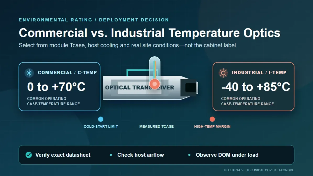
Commercial and industrial temperature grades normally refer to module case temperature, not outdoor weather. An industrial-temperature label also does not make the router, power supply or cabinet able to operate across the same range. Review the actual module in the actual host under worst-case conditions. See 400G Optics in Outdoor Cabinets for the thermal planning workflow.
Record FEC and software with the optic
At 100G and 400G, a physical form factor, reach and connector are not a complete BOM. The applicable FEC mode depends on the interface specification and platform implementation. Cisco's published guidance for its 400G QSFP-DD PAM4 optics, for example, describes host-side RS(544,514) FEC. That is a platform-specific reference, not a universal setting for every 400G design.
For every new optic type, retain the host and port, network OS release, optic part number and revision, peer optic, port mode, FEC setting, and any coherent application or wavelength configuration. This record is more useful than a screenshot that only shows the module was recognized.
Qualify the Combination and Phase the BOM
Test a defined host–optic–peer combination, control substitutions and buy what the current phase can actually use.
Qualify a combination, not an entire brand
Before a larger rollout, validate one representative combination at host level. Check identification, link establishment, traffic forwarding, available digital optical monitoring, FEC or error counters and recovery after an approved restart or reinsertion.
A defensible record says: Router A, line card B, port mode C, software release D and module revision E were tested against peer F over the documented link. It does not silently become a claim that every module from the same supplier works on every platform.
If hardware, firmware or coding changes on a repeat order, disclose and review the change before treating the replacement as equivalent to the qualified item.
Make spares deployment-ready
Long travel times, limited nighttime staffing and remote sites make spare planning more important in rural networks. Record the hosts each spare is approved for, the exact revision or coding where relevant, storage location, matching far-end requirement, and any attenuator, patch cord or passive WDM component needed with it.
A spare is useful when a technician can install it during an outage without reopening the compatibility investigation.
Divide the purchase list by phase
This structure prevents early purchase of optics for an unfinished topology and avoids discovering at installation that the new core port requires a different interface, FEC mode or cooling plan.
Final Rural ISP Upgrade Checklist
- Constraint: Identify whether the bottleneck is at access, aggregation or core.
- Endpoints: Record the exact hosts, line cards or NICs, ports and software releases.
- Route: Document length, measured loss, fiber type, connectors, splices and passive components.
- Interface: Confirm the optical interface—not only the data rate and nominal reach.
- Breakout: Verify host profile, lane mapping, cable type and remote-side interfaces.
- Environment: Check case temperature, module power, airflow and cabinet conditions.
- Settings: Record FEC, port mode and any coherent wavelength or application settings.
- Validation: Define exactly which host, optic, peer, software and link were tested.
- Repeatability: Control substitutions, hardware revisions, firmware and coding changes.
- Spares: Make sure the remote technician can install the spare without new research.
The checklist is not intended to make every optics purchase complicated. It moves the difficult decisions forward, while the engineering and procurement teams still have time to correct a mismatch. Known 10G LR, validated 100G LR4 or short direct-attach cable links can remain simple. The process earns its value on the exceptions: uncertain long-route loss, hot roadside cabinets, mixed-generation access equipment and the first 400G link in the network.
Frequently Asked Questions
Should every rural ISP link move to 100G or 400G?
No. Upgrade the links whose traffic, resilience or growth requirements justify the change. An uncongested access link can stay at 10G while aggregation and core capacity increase elsewhere.
What information is needed before requesting an upgrade optics BOM?
Provide both endpoint models and ports, software versions, current and target speeds, route length or measured loss, fiber and connector types, passive components, environment, FEC requirements, quantity and deployment phase.
Can a 40G LR4 optic be passively broken into four 10G links?
No. A duplex 40G LR4 optic multiplexes wavelengths onto one fiber pair. A 4×10G breakout requires a host-supported lane mode and the appropriate parallel or electrical breakout interface.
Does an industrial-temperature optic guarantee outdoor cabinet operation?
No. The module's case-temperature rating does not qualify the complete host or cabinet. Airflow, port population, optic power, cabinet cooling and the other installed equipment still need review.
When should a rural ISP consider 400ZR?
Consider it when compatible hosts and the optical-line design support coherent operation and the route requires it. Span loss, OSNR, amplification, host software, thermal limits and operational capability must be evaluated together.
Turn the Upgrade Plan Into a Reviewable BOM
Share the host models and ports, current and target speeds, route length or measured loss, fiber path, environment, quantity and rollout phase. Axonode can help separate items that are ready to quote from combinations that still need compatibility or link validation.
Request an optics upgrade reviewTechnical references: Arista Transceiver and Cable Guide; Cisco 400G optics implementation guidance; OIF Implementation Agreements.
Platform and module behavior must be verified against the exact current documentation and deployment conditions before purchase.