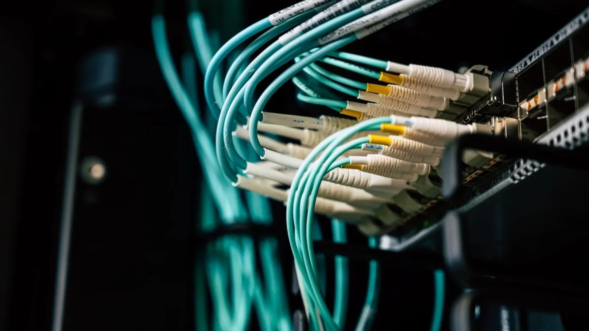
Optical Transceiver Port Flapping: A Fault-Isolation Workflow Before Replacement
Troubleshoot optical transceiver port flapping by separating host, configuration, module, connector, fiber path and optical-power causes before replacement.

Repeated link-up and link-down events do not identify a failed transceiver by themselves. Port flapping can originate in the host configuration, software, module identity, connector condition, cable plant, optical power window or the far-end device. Replacing the optic first may only move the symptom.
Use a controlled sequence. Preserve the first evidence, change one variable at a time and compare both ends of the link before approving replacement or a new optics order.
Freeze the Evidence Before Touching the Link
Capture the time window, event logs, interface state, configured speed, forward error correction (FEC) setting where relevant, alarms and error counters. Record whether the flap affects one port, a group of ports, one chassis, one route or both directions.
| Evidence | Why it matters |
|---|---|
| Exact timestamps | Correlates link events with maintenance, temperature or power changes |
| Both endpoint logs | Separates local symptoms from a far-end reset |
| Interface configuration | Exposes speed, breakout, autonegotiation or FEC mismatch |
| Module identity and diagnostics | Confirms what each host actually reads from the optic |
| Error counters before clearing | Preserves clues that a reboot or reseat may erase |
Do not clear counters or reboot both endpoints before saving the baseline. A clean screen after a reset is not proof that the cause was removed.
Step 1: Classify the Failure Pattern
Ask four fast questions:
- Is the link never stable, or does it operate for minutes or hours before dropping?
- Does the failure follow a module, a port, a patch cord or a fiber route?
- Do both endpoints record the event at the same moment?
- Did the issue begin after a software, configuration, cabling or module change?
A repeatable pattern determines the next test. A port that fails only with one module suggests a different branch from multiple ports failing after a software upgrade. A route that becomes unstable after patch-panel work points toward inspection and path verification before procurement.
Step 2: Verify Host and Port State
Confirm the exact device, line card or network interface card, port, software version and intended operating mode. Check that both ends agree on speed, lane configuration, breakout and any required FEC.
Physical insertion is not complete compatibility. Hosts can differ in how they enforce module coding, expose diagnostics or respond to unsupported identifiers. If the same optic behaves differently across platforms, use the MikroTik and Cisco behavior guide as a framework for separating coding behavior from the optical link.
Do not disable alarms or force settings merely to make the symptom disappear. Record the original state, follow the platform’s documented procedure and preserve a rollback.
Step 3: Inspect the Physical Interface
Shut down or isolate the link as the site procedure requires. Inspect and clean connector end faces with appropriate tools, then reseat the connections. Verify that the patch cord type and connector polish match the equipment and passive path.
Look for:
- Contamination or damaged connector end faces
- A partially seated module or latch
- Tight bends, stress or disturbed patching
- Incorrect fiber pair or reversed mapping
- An unexpected adapter, splitter, MUX or attenuator
- Recent repair points or undocumented patch-panel changes
Cleaning is a controlled maintenance action, not a diagnosis by itself. If stability returns, document what was cleaned and preserve the before-and-after readings where available.
Step 4: Check the Optical Operating Window
Read transmit and receive values at both ends when the host and module support digital diagnostics. Compare them with the exact module specifications and the approved operating limits—not with a generic “normal” range.
Two boundaries matter:
| Boundary | Fault risk |
|---|---|
| Low received power | Route loss, contamination, weak transmitter or a disturbed passive path may leave insufficient margin |
| High received power | A long-reach optic on a short low-loss route may exceed the receiver’s permitted input |
Diagnostics are useful operating evidence, but readable DOM/DDM values do not prove that the module is fully compatible or that the cable plant has passed an insertion-loss test. For route planning, the ISP/WISP backhaul guide shows why the complete path must be matched to the selected optic.
Step 5: Perform Controlled Substitution
Substitute only after the baseline is recorded. Use a known-good item with the same verified interface specification, and change one element at a time:
- Patch cord
- Module at one endpoint
- Module at the other endpoint
- Port, if the platform and maintenance plan permit
- Fiber path or loopback test, if the site procedure supports it
Label every item and result. If module A fails in port 1 but works in port 2, while module B also fails in port 1, the evidence does not support blaming module A alone. If the symptom follows one module across verified ports and paths, replacement becomes more defensible.
Step 6: Decide the Correct Action
| Finding | Next action |
|---|---|
| Configuration or software mismatch | Correct under change control and retest |
| Contaminated or damaged connection | Clean or replace the affected interface and establish a new baseline |
| Optical power outside limits | Revise the path, optic selection or attenuation plan |
| Symptom follows a verified module | Quarantine it and prepare replacement evidence |
| Symptom remains tied to one host port | Escalate host or line-card investigation |
| Cause remains uncertain | Hold a wider rollout and request a structured review |
Avoid labeling the issue “incompatible” unless the evidence identifies which layer failed. Coding rejection, optical mismatch, host configuration and physical-path instability require different corrective actions.
What to Send With a Replacement or Support Request
- Host vendor, model, line card or NIC and software version
- Exact port and configured mode at both ends
- Module labels, part numbers and read-back identity
- Fiber type, route length, connector map and passive components
- Tx/Rx readings, alarms and error counters from both endpoints
- Event timestamps and the observed flap interval
- Controlled substitutions already performed
- Photos of labels and relevant patching, without exposing private site data
- Quantity, required replacement date and whether a sample is acceptable
This turns a vague “the SFP is unstable” request into an evidence set that engineering, procurement and the supplier can review together.
Frequently Asked Questions
Does port flapping always mean the optic is defective?
No. The symptom can come from configuration, host behavior, connectors, fiber loss, excessive receive power, passive components, the far-end device or the module. Isolate the layer before replacing parts.
Can DOM/DDM prove the fiber path is good?
No. It can report module-measured operating values when supported, but it does not replace the appropriate cable-plant test and does not prove complete host compatibility.
Should both optics be replaced as a pair?
Not automatically. Record and test both directions first. Replace the item supported by evidence, while preserving correct paired wavelengths for BiDi links and matched interface specifications for every link.
Why does the link stabilize after reseating the module?
Reseating may temporarily change connector contact, cleanliness, mechanical seating or host initialization. Record the event and continue testing; the improvement alone does not identify the root cause.
What makes a useful known-good module?
It must have a verified interface specification and known behavior in the relevant platform and mode. “It fits the cage” is not an adequate control.
Turn Port Flapping Into a Reviewable Evidence Set
Share both endpoint platforms, module identities, configuration, event logs, optical readings, route details and the results of one-variable substitutions. Axonode can help organize the evidence and determine whether the next step is a compatibility review, path correction, sample validation or replacement BOM.
Review a flapping-link evidence set