
QSFP28 Breakout Selection: What to Check Before Ordering 100G-to-4×25G Links
Plan a 100G-to-4×25G breakout by checking host support, lane mapping, FEC, cable type, endpoint optics and the complete BOM before ordering.
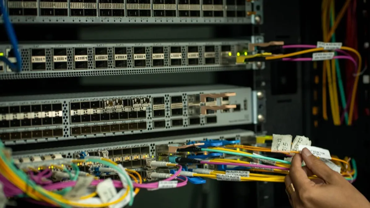
Bottom line: A 100G QSFP28 port can support four 25G lanes on many platforms, but a breakout cable by itself does not create four usable interfaces. Before ordering, confirm that the host supports 4×25G channelization on that exact port, that the media matches that mode, and that every 25G endpoint has the right speed, FEC and compatibility settings.
What are the three ways to build a 100G-to-4x25G link?
There are three ways to build a 100G-to-4x25G link. Pick the path first — it decides the cable, the optics and the checks that follow. LR4 is not a breakout path: it is a single-lane 10 km single-mode optic, so never pair it with an SR4 MPO assembly.
| Path | When it fits | Fiber and reach | Check first |
|---|---|---|---|
| Direct-attach copper (DAC) | Short links inside a rack | Copper cable, fixed length | Length, connector type and host support |
| Active optical cable (AOC) | Short fiber links where pre-terminated ends are acceptable | Fiber, pre-terminated at both ends | Length, connector type and host support |
| Pluggable optics + MPO fanout | When the far ends need separate 25G optics | SR4 on multimode fiber to 100 m; PSM4 on single-mode fiber to 500 m | PMD match, MPO polarity, connector gender and leg labels |
A 100G QSFP28 port can support four 25G lanes on many platforms, but a breakout cable by itself does not create four usable interfaces. The host must support 4×25G channelization on the exact port, the selected media must match that breakout mode, and each 25G endpoint needs the correct speed, FEC and compatibility settings.
The purchasing question is not simply “Which breakout cable length do we need?” It is “Which complete host-to-four-endpoint design has documented support?”
What breakout topology should you define first?
Draw the link before selecting a cable or module. Record the 100G host, the four 25G hosts, the physical route and where the breakout separates.
| Topology input | What to record |
|---|---|
| 100G endpoint | Device, line card, port, software and supported breakout modes |
| Four 25G endpoints | Device, NIC or line card, exact ports and software |
| Media route | Rack, row, pathway, patch panels and accessible service points |
| Breakout location | At the 100G end, near the 25G endpoints or through structured cabling |
| Operating requirement | Ethernet speed, FEC, link acceptance and redundancy |
The breakout location affects cable management and serviceability. A fixed assembly that branches too early or too late can be difficult to route even when its total length is correct.
Does your 100G port support 4x25G breakout?
Use first-party hardware and software documentation for the exact host. Confirm that the specific QSFP28 port supports 4×25G breakout, not only 100G operation.
Check for:
- Supported breakout modes on the exact port
- Required interface or channelization command
- Port-group restrictions and effects on adjacent ports
- Minimum software release
- Supported cable or optical interface families
- Lane and logical-interface naming after breakout
Some 100G optics and ports are not breakout-capable in every operating mode. A QSFP28 form factor or a four-lane electrical interface does not, by itself, prove that the optical assembly and host expose four independent 25G services.
If the host evidence is incomplete, collect the information described in the optical transceiver compatibility check guide before asking for a product match.
Which media architecture should you choose?
The common choices are a passive direct-attach copper (DAC) breakout, an active optical cable (AOC) breakout, or a supported pluggable-optics design with the correct fiber assembly. Each has a different service boundary.
| Media choice | Selection boundary |
|---|---|
| Passive DAC breakout | Use only within the cable length, gauge, bend and host-support limits for the exact assembly. |
| AOC breakout | Treat it as a fixed active assembly; verify end coding, branch length, pathway and replacement access. |
| Pluggable optics plus fiber | Verify that the 100G module exposes a supported 4×25G optical breakout and that the fiber connector, polarity and four 25G interfaces match. |
Do not select by nominal reach alone. Consider pathway congestion, bend radius, airflow, patch-panel use, replacement strategy and whether the site needs a separable transceiver-and-cable design.
For short data-center routes where the main decision is the media type, the DAC and AOC cable collection provides the relevant product family context.
How do you map every lane from the 100G port to the 25G endpoints?
Create a lane map from the 100G port to each 25G endpoint. Label branches consistently at both ends.
- Record the 100G physical port.
- Record the four logical interfaces created by the breakout command.
- Assign each logical lane to one branch.
- Map each branch to a specific 25G host and port.
- Record the cable or fiber identifier for that branch.
- Verify link state and counters lane by lane.
This step prevents an apparently random endpoint outage that is actually a swapped branch, incorrect port map or incomplete channelization.
For parallel-fiber designs, document connector type, key orientation, gender or pinning where applicable, and the selected polarity method. A cable with the right connector family can still be wrong for the installed cassette or module interface.
How do you align FEC and port configuration on every branch?
Each 25G lane may have host-specific forward error correction (FEC) requirements. Determine the applicable FEC behavior from the exact 100G and 25G platform documentation and the selected media.
Record for every branch:
- Configured and operational speed
- FEC mode at both ends
- Auto-negotiation or link-training requirement, if applicable
- Advertised and accepted media type
- Error counters used for acceptance
Do not assume that one working branch proves the other three are configured correctly. Review and test all four.
The 25G BiDi upgrade guide provides a broader example of why FEC, host support and the physical fiber path must be checked together at 25G.
What coding and compatibility checks do the endpoints need?
A breakout assembly has five host-facing ends: one QSFP28 end and four SFP28 ends. Each side may have a different coding requirement.
Provide the supplier with:
- Exact vendor and platform at the 100G end
- Exact vendor and platform for each 25G end
- Software versions
- Required part-number identities or coding profiles
- DOM/DDM visibility requirements for active optical media
- Whether all four endpoints are identical or mixed
Do not write “Cisco-compatible” or “Mellanox-compatible” as the complete requirement. Platform and software details are necessary because support can vary within one vendor family.
How should you validate a representative assembly before rollout?
For a new host combination or a larger rollout, validate the exact assembly and length before releasing the full order.
The controlled check should include:
- Recognition at the QSFP28 and all four SFP28 ends
- Correct logical interface creation
- Link state on all four branches
- FEC state and error counters
- Traffic on each lane and, where relevant, simultaneous traffic across all lanes
- Branch labels and physical routing
- DOM/DDM readings when supported
- Reboot, reseat or configuration persistence if required by the rollout plan
A sample that links on one branch but not the others is not a passed breakout validation.
What belongs in a deployment-ready breakout BOM?
The bill of materials should identify more than “one breakout cable.” Include the host combinations, assembly type, total length, branch length, coding at each end, connector details, labels, spare quantity and acceptance status.
| BOM field | Required decision |
|---|---|
| Assembly identity | Passive DAC, AOC or pluggable-optics design |
| End configuration | QSFP28 at the 100G end and four defined 25G endpoints |
| Length and geometry | Total route, branch point and branch lengths |
| Host coding | Exact coding requirement at all five ends |
| Lane map | Logical interface to physical branch and endpoint |
| Acceptance status | Documentation review, sample result and remaining limits |
Use the optical transceiver upgrade checklist when the breakout is part of a broader speed migration.
What do buyers ask most about 100G-to-4x25G breakout?
Can every 100G QSFP28 port break out to four 25G ports?
No. Breakout support depends on the exact host, port, line card, software and media. Confirm 4×25G support in first-party platform documentation.
Can I use any QSFP28 module with a breakout fiber cable?
No. The selected module must expose a supported breakout interface, and its connector, lane arrangement and optical specifications must match the fiber assembly and four remote interfaces.
Is a QSFP28-to-4×SFP28 DAC always the simplest option?
It can simplify short direct connections, but only when the exact hosts support the assembly and the length, bend, airflow and routing constraints are acceptable.
Does each 25G branch need separate FEC verification?
Yes. Record the applicable FEC mode and error behavior for every endpoint. One working lane does not validate the remaining branches.
Can the four 25G endpoints use different switch vendors?
Potentially, but each endpoint needs its own host and coding review. A mixed-vendor breakout should be specified branch by branch.
What information is needed for a breakout quotation?
Provide all host models and software versions, the 100G port, four 25G ports, breakout mode, media choice, route and branch lengths, FEC requirements, connector or polarity details, coding needs, quantity and validation plan.
How do you prepare the five-endpoint breakout review?
Share the 100G host, four 25G endpoints, software versions, port and FEC requirements, route geometry and preferred media architecture. Axonode can help organize the breakout BOM, identify missing compatibility evidence and coordinate a sample review before rollout.
Review a breakout BOM