400G-to-4×100G Breakout Planning: Port, Optics and Cabling Checks
Plan a 400G-to-4×100G breakout by verifying host mode, lane map, DR4 optics, remote PMDs, MPO polarity, FEC, cable reach and validation evidence.

Bottom line: A 400G port can break out into four 100G links only when the host, 400G optic, four remote interfaces, lane map, FEC settings and fanout cabling implement the same topology. This eight-check plan helps network engineers verify that topology before ordering, so a breakout does not fail on a port, optic or cable that was never checked.
The eight checks at a glance
Work through this list in order. If any row fails, stop and fix it before ordering — a breakout that fails one check will not be saved by the other seven.
| Check | Question to answer | Evidence to keep |
|---|---|---|
| 1. Parent port | Can this exact port break out to 4 x 100G? | Vendor and software documentation for this port |
| 2. 400G optic | Is the optic breakout-capable and in the supported family? | Optic model and breakout support confirmation |
| 3. Remote endpoints | What is at the far end of each of the four legs? | Endpoint, port and optic for each leg |
| 4. Remote PMD | Does each remote optic match the leg it serves? | Remote optic type per leg |
| 5. MPO fanout | Does the assembly match the fiber, polarity, gender and labeling? | Cable type, polarity and labels per leg |
| 6. Optical budget | Does each leg have enough budget for its own span? | Per-leg loss calculation |
| 7. Commissioning | Can every leg be tested under change control? | Test result per leg |
| 8. BOM | Is every item on one deployment-ready list? | Final bill of materials |
The QSFP-DD or OSFP form factor alone does not guarantee breakout, and a cable with the right connectors does not prove optical interoperability.
Plan the design as five ports and four end-to-end links: one 400G parent port plus four independent 100G child endpoints.
Step 1: Does this parent port support a 4×100G breakout?
Record the chassis, line card, 400G port and software version. Confirm in the official platform documentation that the port supports a 4×100G breakout mode with the selected optical architecture.
| Parent-port input | What to verify |
|---|---|
| Port identity | Exact slot and port, not only the switch family |
| Software | Release that exposes the required breakout mode |
| Lane mode | Four 100G child interfaces mapped from the parent |
| Optical PMD | Interface supported with the selected 400G optic |
| FEC behavior | Parent and child requirements documented |
If the platform exposes only one 400G interface for that optic or port mode, stop. Do not purchase fanout cabling to create a mode the host does not support.
Step 2: Is this 400G optic breakout-capable?
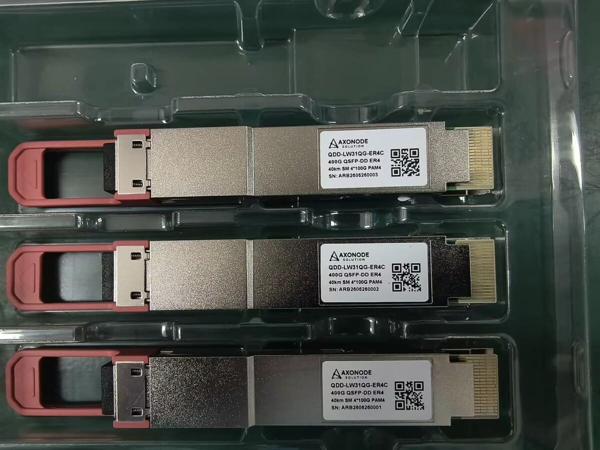
Selected DR4-family implementations can map four optical lanes to four remote 100G interfaces, but capability is module-specific. Check the exact part number, reach class, connector, host approval and data-sheet breakout statement.
Do not treat FR4 as a conventional 4×100G optical breakout. FR4 carries wavelength-multiplexed lanes over a duplex fiber pair, while a DR4 breakout exposes parallel optical paths through MPO.
If the project has not yet chosen between parallel and wavelength-multiplexed 400G interfaces, resolve that architecture first. The breakout BOM must stand on its own verified host, optic and cabling specifications.
Step 3: What is at the far end of each of the four links?
Create a row for each child link before selecting the cable.
| Child link | Required record |
|---|---|
| 100G-1 | Device, port, software, PMD, optic and cable length |
| 100G-2 | Device, port, software, PMD, optic and cable length |
| 100G-3 | Device, port, software, PMD, optic and cable length |
| 100G-4 | Device, port, software, PMD, optic and cable length |
The remote ports may be on four devices, two devices or one chassis, but each is an independent compatibility and loss-budget decision. Do not approve a generic “4×100G side” with unknown hosts.
Step 4: Does each remote 100G optic match its leg?
The four remote 100G optics must match the optical lanes presented by the breakout-capable 400G optic. A 100G form factor does not define the PMD. Compare wavelength, lane rate, FEC, reach, fiber and connector requirements.
If the remote port expects a duplex LC 100G interface while the 400G fanout exposes a parallel single-lane path, a passive harness cannot perform the optical conversion. Select remote optics explicitly supported for the topology or revise the design.
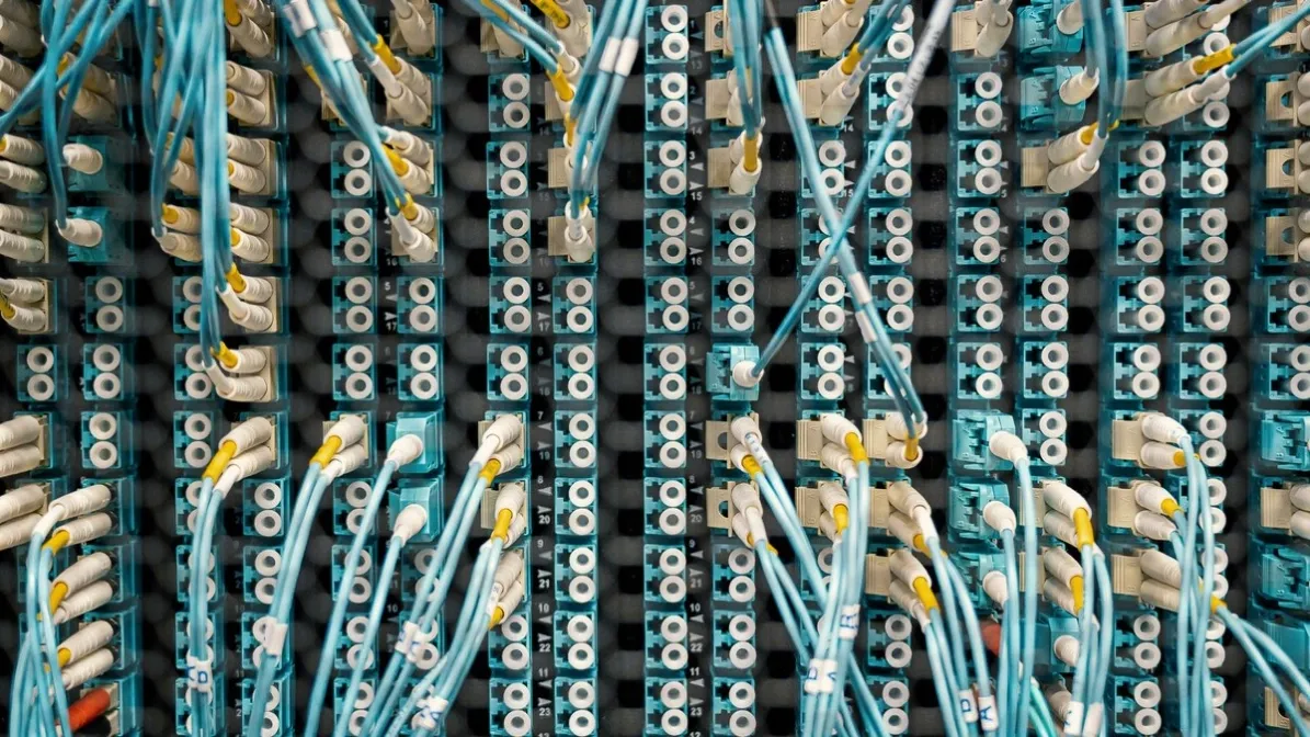
Step 5: Does the MPO fanout assembly match the fiber, polarity, gender and labeling?
Control the physical details:
- MPO connector type, gender and key orientation at the 400G optic
- Fiber count and single-mode fiber specification
- Polarity and pin mapping
- Four branch connectors and their matching remote optics
- Branch labels 1–4 aligned with the host lane map
- Trunk and branch lengths, bend limits and routing
- Connector cleanliness and inspection method
A mislabeled fanout can make a technically correct design operationally unmanageable. Label the parent port and all four child links before installation.
Step 6: Does each leg have enough optical budget for its own span?
Do not calculate one average loss for the fanout. Each child route can have different fiber length, connector count and passive transitions.
For each link, compare:
Selected 400G lane transmitter → fanout branch and route loss → selected 100G receiver limits
Then calculate the reverse direction using the remote transmitter and the applicable receiver lane at the 400G module. Check low-power margin and maximum receive input in both directions.
The ISP/WISP backhaul optics guide provides the route-input framework when these child links extend beyond one data-center row or building.
Step 7: How should the breakout be configured and commissioned?
- Save the parent-port configuration and rollback procedure.
- Apply the supported breakout mode.
- Verify that four child interfaces appear with the expected identifiers.
- Install inspected optics and fanout cabling.
- Bring up one child link at a time.
- Confirm FEC, alarms, error counters and available optical readings.
- Map the logical child interface to the physical branch label.
- Save the final baseline and spare identities.
Do not accept “all four LEDs are green” as the complete commissioning record. The mapping and interface state must be useful for later troubleshooting.
Step 8: Is every item on one deployment-ready BOM?
| BOM group | Required lines |
|---|---|
| Parent | Exact 400G optic and compatible host profile |
| Remote | Four exact 100G optics matched to the breakout PMD |
| Cabling | MPO fanout assembly with polarity, gender and branch lengths |
| Operations | Labels, cleaning/inspection items and approved spares |
| Validation | Sample, test method, acceptance criteria and evidence status |
Axonode’s sourcing support can coordinate these lines as one topology instead of quoting a 400G optic, four 100G optics and a cable without a verified relationship.
Frequently Asked Questions
Can every 400G QSFP-DD port break out to 4×100G?
No. The exact platform, line card, software, port and selected optic must support the mode.
Can a 400G FR4 optic be used with a passive 4×100G fanout?
Do not assume so. Conventional optical breakout uses accessible parallel lanes, while FR4 multiplexes wavelengths onto a duplex pair.
Are four identical 100G optics always required?
The four interfaces normally need to match the optical PMD presented by the breakout, but exact remote host coding may differ. Review each endpoint row separately.
Does the fanout cable determine the breakout lane order?
It implements a physical mapping, which must align with the host and module lane definition. Document branch 1–4 rather than relying on cable color alone.
What should be tested before volume rollout?
Test the exact parent port, 400G optic, fanout assembly and at least the representative remote host/optic combinations under the required port mode and FEC.
Send All Five Ports for One Breakout Review
Share the parent platform and mode, exact 400G optic, four remote endpoints, PMDs, FEC, MPO mapping, branch lengths and loss evidence. Axonode can help organize the topology and identify which BOM lines still need host or link validation.
Review a 400G breakout BOM