CWDM MUX/DEMUX Project BOM: Channels, Loss and Expansion Checks
Prepare a CWDM MUX/DEMUX BOM by checking the wavelength plan, fiber path, passive loss, ports, transceivers, upgrade capacity and validation inputs.
A CWDM project BOM must make the entire optical path visible. Ordering a pair of MUX/DEMUX units and several colored transceivers is not enough if the channel plan, device ports, connector path, insertion loss and future expansion rules are still unclear.
The safe sequence is to define the services and fiber constraint, reserve wavelengths, build both end-to-end paths, calculate the loss using the exact passive components and then lock the transceiver and MUX/DEMUX identities.
What the plan must record
| Planning input | Decision it supports |
|---|---|
| Current and future services | Channel count and reserved capacity |
| Fiber strands and route | Working, protection and maintenance topology |
| Service rates and interfaces | Transceiver family and host-port requirements |
| Route length and measured loss | Optical budget and passive-loss allowance |
| Operational model | Fixed channel ownership, labels, spares and restoration |
Budget first: the complete passive path
The CWDM link budget should include fiber attenuation, connectors, splices and the insertion loss of every passive element in the selected port path. Use the exact MUX/DEMUX specification rather than a generic allowance copied from another design.
Calculate each direction. If the topology is not symmetrical, the losses may differ. A route that includes an upgrade port, monitor tap, patch panel or additional passive stage should be represented as it will actually be installed.
Keep measured, documented, estimated and unknown values separate. An estimated total can support preliminary selection, but it is not the same evidence as a measured cable plant and commissioned link.
Phase 1 — Plan the channels
Define the capacity problem first
Start by checking the network's service requirements before ordering CWDM hardware. Record the current service count, required data rates, endpoint locations, available strands, expected expansion and restoration plan. Then compare CWDM with other valid options rather than treating it as a default.
If additional fiber pairs are available, they may deliver the same services with less complexity. CWDM earns its place when fiber is constrained, services share the same physical route, or protection and future growth require it.
Build a wavelength plan before selecting part numbers
Build a wavelength plan to define each channel's use and reservation state. Assign each wavelength to one clearly identified service, including a protection channel, future expansion or spares, so no wavelength is double-assigned.
One channel record contains:
| Channel record field |
|---|
| the wavelength |
| service |
| direction |
| endpoint ports |
| transceiver identity |
| MUX/DEMUX port |
| operational owner |
Avoid changing a wavelength assignment after installation, because it changes the transceiver, port and documentation for that service.
Phase 2 — Specify the hardware
Confirm the MUX/DEMUX port architecture
Confirm the exact MUX/DEMUX part number, its port count, supported wavelength map, connector type and insertion loss. Do not assume that every unit in a family has the same port options.
| Port | What to verify |
|---|---|
| Common line | The single fiber path carrying all wavelengths |
| Channel ports | Wavelength-to-port mapping |
| Upgrade port | Additional channels and capacity |
| Monitor port | Tap ratio and measurement use |
| Expansion port | Future transceiver or service additions |
| Network ports | Host service requirements |
Match transceivers to channels and hosts
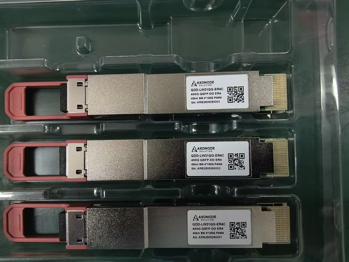
Select one CWDM transceiver per service and confirm that its wavelength, rate, reach, temperature and port number match the assigned channel.
Use a controlled test to determine whether the supplier's approach will protect the project when a link, line card or host software changes. Distinguish a test from a product claim.
A color mismatch can shut down a single service without affecting other channels. Label each transceiver with wavelength, service, endpoint port and host identity before installation.
Plan expansion without hiding today’s loss
Do not treat optional ports or future capacity as free. Record the channel reservations for each reserved wavelength, its loss allowance and who owns each oxygen line.
Place unused capacity under the same loss accounting as active channels. The spare lines and wavelengths are not free: they consume the same passive budget. Plan the upgrade and monitor ports as passive stages with their own insertion losses.
Insist on complete documentation for the supplier warranty and do not accept informal material. Record the model and port assignment of each route.
Phase 3 — Install and prove it
Prepare the physical installation record
Prepare a cable record before ordering hardware by checking the wavelength plan, fiber count, passive loss, transceivers, upgrade capacity and validation signals.
Document rack location, power and grounding, patch-panel assignment, MUX/DEMUX port labels, spares and physical access. A common-installation record should be reusable for channel-level maintenance.
Define commissioning and acceptance
Write the acceptance steps before any equipment is installed.
- Record the first and last values of every relevant meter.
- Fix the fiber route and patch panels.
- Confirm the MUX/DEMUX port assignment.
- Confirm and validate every transceiver.
- Test each channel in isolation, then bring the full set up.
- Record DOM readings for each channel.
- Capture a baseline for later comparison.
DOM/DDM monitoring is the best option for confirming channel receive power and temperature, but it is not a replacement for testing the transceiver after installation.
Six questions before the order
Can a supplier be judged by the price of one module alone?
No. A module identity should be checked against the requirements for its batch and firmware version. The supplier's documentation should state the identity and batch detail, and it should be used for the project.
What are common countermeasures for port flapping?
Common countermeasures include replacing the patch cord, replacing the module, replacing the port and fiber connection and taking a different link path. Controlled substitution is designed to isolate which item resolves the issue and why.
What does an approval pack prove?
That a specific model is a defensible candidate for an identified deployment, with a known requirement, evidence level and decision. It is not a universal compatibility guarantee.
What counts as a defect in a module?
A persistent defect across ports and known-good conditions. One flap in a single port does not prove a defect by itself.
Should I use a test module with a known-good cable?
Yes. Test one component at a time and use known-good items.
What details do I send with a support request?
Host, module, software, configuration, link state and evidence. A timeline of each failure and the first and last values of every relevant counter help the support team identify the cause faster.
The final BOM check
| Final BOM check |
|---|
| Channel plan with wavelength and service owner for every use |
| Both MUX/DEMUX units, port maps and part numbers |
| One transceiver identity per service and direction |
| Fiber budget for both directions |
| Loss accounting for upgrade and monitor ports |
| Measured route condition, not an assumed value |
| Commissioning steps and operating baseline |
| Label standard for channels, ports and patching |
| Spare transceivers and monitoring position |
| Change rule for reserved wavelengths |
Prepare the Wavelength Plan Before Ordering Hardware
Do not allow a general approval to stand in for an undocumented exception. If approved with conditions, the approval record should explain the conditions on which it depends:
Request a project reviewDo not treat optional ports as free capacity. An unused upgrade path and monitor tap each change the loss budget.