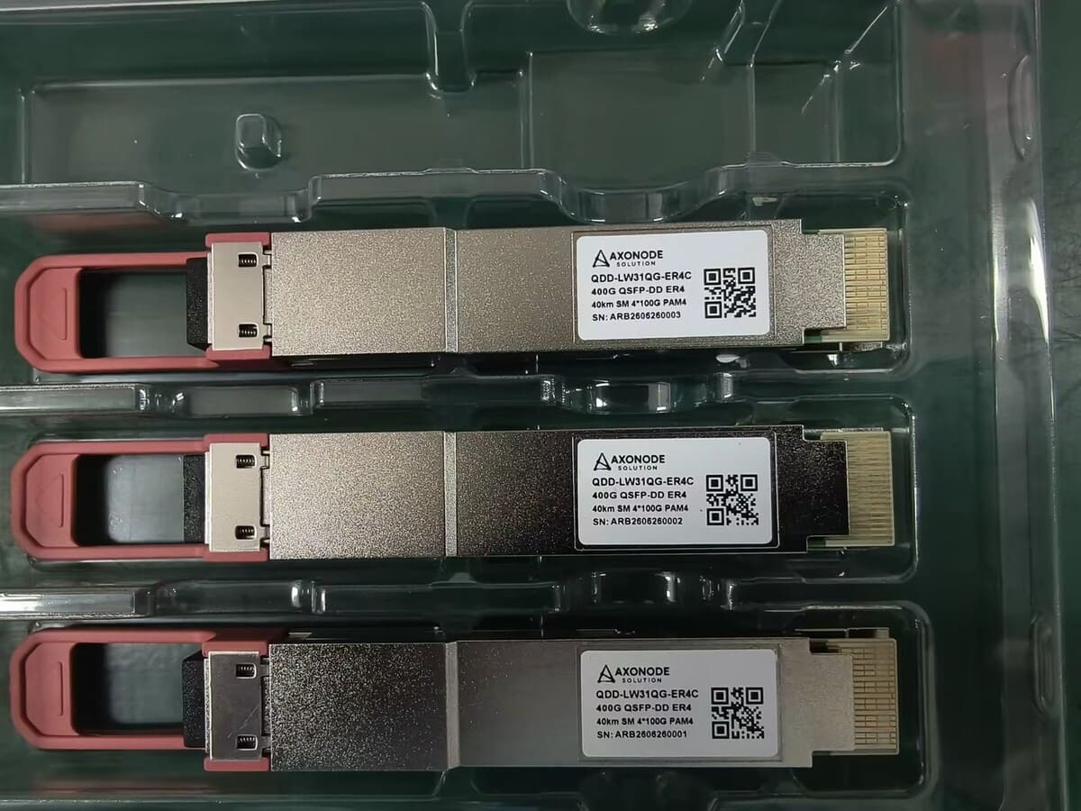
Can 100G LR4 or CWDM4 Optics Pass Through a Passive CWDM MUX?
Do not approve 100G LR4 or CWDM4 through a passive CWDM MUX from a 1310 nm label alone. Check spectrum, passband, loss, isolation and endpoints.
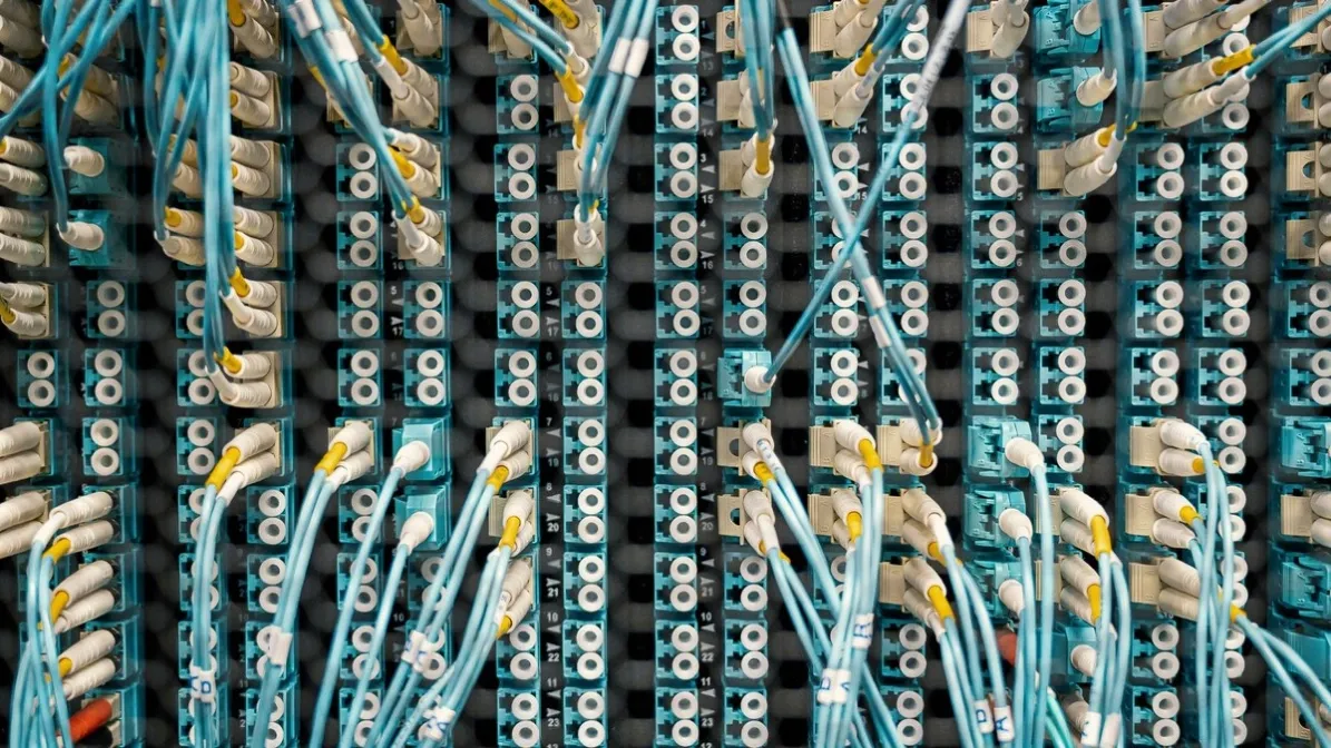
No - not channel by channel. 100G LR4 and CWDM4 QSFP28 modules already multiplex four wavelengths inside the module, so they do not plug into a passive CWDM MUX channel-by-channel. A passive CWDM MUX wants one CWDM SFP/SFP+ per channel, each on its own grid wavelength. The full transmitted spectrum must fit the exact passive path, and the complete optical budget and endpoints must remain valid.
In many standard deployments, a conventional single-channel CWDM port is not an automatic match for a multi-lane 100G LR4 or CWDM4 signal. The correct answer is component-specific and often requires a different passive path or interface choice - confirm against the module datasheet.
LR4 vs CWDM4 vs a CWDM SFP on the Transport Grid
| Interface | Wavelengths | Reach | How it uses a MUX |
|---|---|---|---|
| 100G LR4 | LAN-WDM, about 1295-1310 nm, four lanes inside one QSFP28 | 10 km | Not one lane per MUX channel - the four lanes travel together |
| 100G CWDM4 | 1271 / 1291 / 1311 / 1331 nm, four lanes inside one QSFP28 | 2 km | Not one lane per MUX channel - the four lanes travel together |
| Individual CWDM SFP / SFP+ | Transport grid, ITU-T G.694.2, 20 nm spacing, 1271-1611 nm - one wavelength per module | Per channel - confirm against the module datasheet | One module per MUX channel - this is what a passive CWDM MUX expects |
Wavelengths and reaches above are the standard values for each interface; confirm the exact values against the module datasheet for the module you plan to order.
The Overlap That Causes the Mistake: CWDM4 Lanes Sit on CWDM Channels 1-4
CWDM4's four wavelengths - 1271, 1291, 1311 and 1331 nm - coincide with CWDM grid channels 1-4. That coincidence is the trap. CWDM4 is a 100G data-center interface, not transport CWDM: its four lanes are multiplexed inside the QSFP28 and must arrive together at a matching 100G receiver. A passive CWDM MUX, by contrast, splits those wavelengths apart, sending each one to a different channel port.
The same trap appears with a grey 1310 nm module. A grey 1310 nm module is not the same as CWDM channel 3 (1311 nm): one is a single-wavelength grey interface labelled by its nominal wavelength, the other is a defined channel on the CWDM grid with its own passband. A single nominal label can hide multiple optical lanes. 100G LR4 uses several LAN-WDM wavelengths around the 1310 nm region. CWDM4 also combines four defined wavelength lanes inside the module. A passive CWDM line system, by contrast, routes signals according to its own port passbands on the CWDM grid.
The question is not whether one printed wavelength falls near another. It is whether every optical lane passes through the device with acceptable attenuation and distortion. Do not approve the path from 1310 nm, CWDM or the transceiver form factor alone.
Why the Module Cannot Go Through the MUX Channel by Channel
A passive CWDM MUX port has a defined spectral passband, insertion loss and isolation. The full transmitted spectrum must fit the exact passive path. The names use wavelength-division principles for different interface specifications:
- 100G LR4: a 100G optical interface over duplex single-mode fiber using multiple wavelength lanes. Use the exact module and standard documentation for its wavelength and power limits.
- 100G CWDM4: another defined 100G multi-wavelength duplex interface. Its wavelength set and reach conditions are not interchangeable with a generic fixed CWDM transceiver channel.
- Passive CWDM line system: a MUX/DEMUX that combines or separates line-system channels on ports with specified passbands. It does not automatically act as a transparent 1310 nm pipe for every multi-wavelength client interface.
A passive component cannot convert LR4 into CWDM4 or correct a host/FEC mismatch. Both endpoints must use matching 100G interfaces and supported host configurations.
What to Use Instead
| Requirement | Architecture to investigate |
|---|---|
| Direct point-to-point 100G over one fiber pair | Matching LR4 or CWDM4 endpoints without an incompatible channel filter |
| Carry 100G as one service over a WDM line system | Use an interface and line-system design explicitly intended for that client/line relationship |
| Expand several services on one fiber pair | Build a documented CWDM or DWDM channel plan with matching transceivers |
| Pass multiple client wavelengths transparently | Select passive components whose verified passband covers the complete spectrum and loss requirements |
Do not try the 1310 port in production as the design method. An apparent link-up can still have inadequate lane margin or unstable behavior.
The fiber-expansion solution helps compare WDM and BiDi strategies before forcing a client optic through an unsuitable passive line system.
Loss-Budget and Wavelength Checks Before Ordering
Work through these five gates before ordering, and check each item in the table below against the exact datasheets - not against a marketing label.
| Item | What must be reviewed |
|---|---|
| 100G optic | Complete wavelength set, spectral limits, output and receiver specifications |
| CWDM MUX port | Center wavelength, passband, insertion loss, isolation and direction |
| Common path | Fiber, connectors, splices and every other passive component |
| Endpoints | Matching 100G PMD, host support, FEC and optical limits |
- Gate 1 - Complete optical spectrum: obtain the exact wavelength-lane information for the proposed LR4 or CWDM4 optic. Do not use only the marketing center-wavelength label.
- Gate 2 - Exact passive port path: identify the MUX/DEMUX model, channel port, common port and every OADM or cascade in the route. Use the specified passband and loss for that exact path.
- Gate 3 - Passband alignment: confirm that the passive path passes the entire required spectrum with the performance needed by the selected interface. If any lane lies outside the supported passband, reject the path or obtain authoritative engineering approval for a different device.
- Gate 4 - Optical budget and receiver window: add the MUX/DEMUX loss to fiber, connectors, splices and other passive loss. Calculate both directions and compare them with the exact transceiver limits, including maximum receive input.
- Gate 5 - Matching endpoints and host mode: both endpoints must use matching 100G interfaces and supported host configurations. A passive component cannot convert LR4 into CWDM4 or correct a host/FEC mismatch.
What to request from the passive-device supplier
- Exact model and revision
- Channel and common-port map
- Center frequency or wavelength and passband definition
- Maximum and typical insertion loss for the used path
- Isolation and return-loss specifications where applicable
- Connector type and handling requirements
- Cascading or OADM conditions
- Any verified application note for the exact 100G interface
Do not accept a generic supports 1310 nm statement without a spectral definition and exact path.
A Controlled Validation Plan
If authoritative specifications indicate the path may be viable but evidence is incomplete, define a controlled test before deployment. Record the exact optics, hosts, software, passive devices, patching and route loss. Verify link state, FEC, alarms, error counters and available per-lane or module diagnostics under the intended configuration.
Testing one unit does not create universal compatibility. The result applies to the documented component combination and conditions. Axonode's sample-testing support can help define the evidence needed before a larger optics or passive-component order.
Frequently Asked Questions
Can a 100G LR4 optic use the 1310 nm port of any CWDM MUX?
No automatic approval is justified. Check the full LR4 spectrum against the exact port passband, loss and isolation, then verify the complete link budget and endpoints.
Is 100G CWDM4 the same as a CWDM line-system channel?
No. CWDM4 is a defined 100G client optical interface using multiple wavelengths. A line-system channel is a passive filtering path with its own grid and passband.
Can a passive CWDM MUX convert LR4 to CWDM4?
No. Passive filtering does not convert one 100G PMD into another. The endpoints must use matching interfaces or an explicitly designed conversion platform.
If the link comes up, is the path approved?
No. Check error performance, FEC, optical margin, alarms and stability under the intended conditions. Link-up alone does not prove every lane has adequate margin.
What should be sent for a passive WDM path review?
Send both hosts, exact optics, full data sheets, passive-device models and port paths, fiber route, measured loss, FEC, available optical readings and the intended channel plan.
Send Your Platform, Distance and Quantity to Check Options
Before you order optics or a MUX for this link, send the platform and host details, the distance, the quantity and the exact module and passive-device models you are considering. That is the fastest way to find out whether the proposed path has sufficient documented evidence - or whether a different interface, passive device or controlled sample test is the safer choice.
Send your platform, distance and quantity to check options