100G Single-Lambda or LR4? What to Check Before Choosing QSFP28 Optics
Compare 100G single-lambda and LR4 QSFP28 optics by exact PMD, host support, FEC, fiber path, interoperability, optical budget and rollout plan.
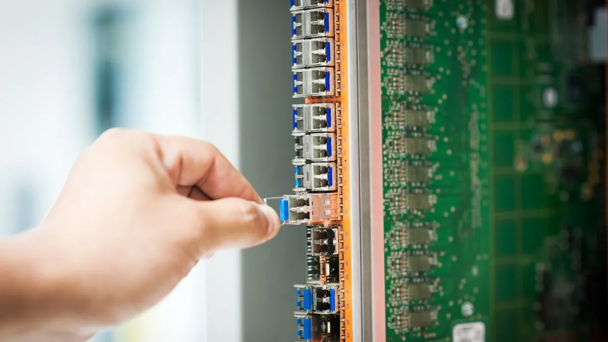
Two QSFP28 modules can both be labelled 100G, fit the same cage and quote a similar reach — and still not link. The check that decides the purchase is not the label on the box; it is the exact optical interface required at both ends. This guide puts that comparison first, then works through host support, FEC, the fiber path and a pre-order checklist, so the interface is named before anything is ordered.
Single-Lambda (DR1 / FR1 / LR1) vs LR4 at a Glance
Use this table to name the interface before comparing anything else. DR1, FR1 and LR1 are the single-lambda family members covered here; LR4 is the multi-wavelength interface on the other side of the decision.
| Interface | Optical lanes | Modulation | Reach | Connector | FEC note |
|---|---|---|---|---|---|
| DR1 | One wavelength — the 100G signal on a single lambda | Confirm against the datasheet/supplier | Confirm against the datasheet/supplier | Single-mode path; confirm connector type and polish against the datasheet/supplier | FEC can differ by interface and host — record and align the required mode at both endpoints |
| FR1 | One wavelength — the 100G signal on a single lambda | Confirm against the datasheet/supplier | Confirm against the datasheet/supplier | Single-mode path; confirm connector type and polish against the datasheet/supplier | FEC can differ by interface and host — record and align the required mode at both endpoints |
| LR1 | One wavelength — the 100G signal on a single lambda | Confirm against the datasheet/supplier | Confirm against the datasheet/supplier | Single-mode path; confirm connector type and polish against the datasheet/supplier | FEC can differ by interface and host — record and align the required mode at both endpoints |
| LR4 | Multiple optical wavelengths across the fiber pair | Confirm against the datasheet/supplier | Confirm against the datasheet/supplier | Single-mode path; confirm connector type and polish against the datasheet/supplier | FEC can differ by interface and host — record and align the required mode at both endpoints |
This guide does not state reach or modulation figures for any row — confirm each one against the datasheet/supplier before ordering.
Do not choose between 100G single-lambda and LR4 optics from the shared QSFP28 form factor or a similar reach label. They represent different optical physical-medium interfaces, and the exact host, remote endpoint, FEC behavior and module specification must agree.
Same speed, same connector and a similar reach label do not mean the two ends will link.
The practical decision begins with the interface required at both ends. Then confirm host support, cable plant, optical budget, connector path, coding and validation evidence before converting the result into a BOM.
When to Choose Which
The choice follows the interface each end already requires — match the PMD to the host and the remote endpoint before comparing anything else.
Choose a single-lambda interface (DR1 / FR1 / LR1) when…
A platform designed for a supported single-lambda PMD may favor a different product and upgrade path.
Choose LR4 when…
An existing LR4 fleet may favor continuity in interface identity, spares and troubleshooting knowledge.
Neither conclusion should be applied without checking the actual hosts and project economics.
Consider:
- Installed module and spare inventory
- Approved host-to-optic combinations
- Remote endpoint capabilities
- Cable-plant and patching standard
- Monitoring and diagnostics requirements
- Supplier continuity and change control
- Pilot, rollback and migration sequence
The 100G QSFP28 product category can support product discovery after the interface has been defined.
Start With the Exact PMD Name
“100G QSFP28” describes a rate and form factor, not one optical interface. Record the full interface or physical medium dependent (PMD) designation stated by the host and module documentation.
100G LR4 uses multiple optical wavelengths across the fiber pair. A single-lambda 100G interface carries the 100G optical signal on one wavelength using a different optical architecture. These interfaces should not be treated as interchangeable merely because both modules fit QSFP28 ports.
| Identity field | What to record |
|---|---|
| Host support | Device, line card or port, software release and supported PMD |
| Module identity | Exact OEM reference and requested compatible replacement |
| Remote interface | Exact module and PMD at the far end |
| Electrical behavior | Host lane mode and required FEC behavior |
| Optical path | Fiber type, connector path, route length, loss and passive devices |
If the broader decision is still 100G reach or topology for an ISP link, start with the ISP/WISP backhaul optics guide before narrowing the interface.
Treat Interoperability as an Interface Question
Two standards-based modules can interoperate only when they implement compatible interfaces and both hosts support the required operation. LR4 at one end and a different single-lambda PMD at the other should not be approved from the common data rate.
Do not rely on shorthand such as “LR” without the exact suffix or part number. A quotation, BOM or installed-inventory record that truncates the identity can hide a non-interoperable endpoint.
For replacements, capture the original module label, device inventory output and port documentation. When evidence conflicts, place the row on hold rather than selecting the closest-sounding product.
Verify Host Support and Software
The port cage must physically accept the module, but the platform must also support the exact PMD, electrical interface, power class, thermal behavior, management interface and software release.
Use the host vendor’s compatibility information for the exact platform and port. Record whether the evidence comes from documentation, coding review, a controlled sample or the same field context. Do not generalize a successful result from one chassis or network operating system release to every QSFP28 platform.
The optical transceiver compatibility check provides the host, port and software inputs required before compatible optics are requested.
Review FEC at Both Endpoints
Forward error correction (FEC) requirements can differ between optical interfaces and host implementations. Record the required FEC mode, whether it is mandatory, configurable or fixed on the platform, and how the remote endpoint will be configured.
Do not assume that a link is approved because each module is recognized. A host can read the module while the endpoint FEC or PMD configuration remains wrong. The pre-deployment test should check link state and relevant error evidence, not only inventory recognition.
If a port group shares configuration or lane resources, document the impact before changing one link. The exact platform guide controls the supported behavior.
Compare the Fiber Path and Optical Budget
Both options require a suitable single-mode path for their specified interface. The choice still depends on the exact connector, fiber route and optical limits of the selected modules.
| Path check | Decision risk |
|---|---|
| Connector type and polish | A physical or polish mismatch can block or degrade the link |
| Route length | Supports reach selection but is not a complete loss budget |
| Measured path loss | Provides stronger evidence than distance alone |
| Patch panels and splices | Add loss and possible reflection or contamination points |
| Passive WDM components | Must support the wavelength and add their specified insertion loss |
| Short low-loss path | May require checking the receiver’s maximum input or overload limit |
Compare the estimated or measured path with the exact transmitter and receiver limits in both directions. Preserve the approved engineering margin. A nominal reach label is not a guarantee for an undocumented cable plant.
Build the Validation Plan Before the Volume Order
For a new host or new interface combination, define a controlled sample scope. The sample should represent the exact device, port, software, remote endpoint, fiber path and configuration that matter to the rollout.
At minimum, record module recognition, configured speed and interface, FEC state, link state, alarms, relevant error counters and optical readings where the platform exposes them. Compare the readings with the module limits and approved cable-plant evidence.
Readable DOM/DDM data is useful operating evidence. It does not prove that the coding, PMD, FEC and full link context are correct.
Final 100G Interface Decision Checklist
- The exact PMD is recorded at both ends.
- Both host platforms, ports and software releases support the selected interface.
- The electrical lane and FEC requirements are explicit.
- The two endpoint modules implement compatible optical interfaces.
- Connector, fiber type, route length and passive path are verified.
- Both low-power margin and high-power receiver limits are checked.
- Coding and DOM/DDM requirements are attached to exact hosts.
- Samples, production quantities and spares are separated.
- Acceptance, rollback and evidence ownership are defined.
Frequently Asked Questions
Are 100G single-lambda and 100G LR4 modules interchangeable?
Do not assume so. They use different optical architectures and PMD identities. Both endpoints and hosts must support the same compatible interface.
Does a QSFP28 cage support every 100G QSFP28 optic?
No. Physical form factor is only one condition. Verify the exact platform, port, software, power, thermal, management and interface support.
Can LR4 at one end link to a single-lambda module at the other?
Not merely because both are 100G. Approve a link only when the exact two modules implement compatible PMDs and the endpoints are configured accordingly.
Is FEC always the same for 100G QSFP28 optics?
No. FEC requirements depend on the interface and host implementation. Record and align the required mode at both endpoints.
Is route length enough to choose the optic?
No. Include fiber type, connector and splice loss, passive components, engineering margin and the receiver’s low- and high-power limits.
What should be sent for a 100G interface review?
Send both host models, ports and software versions, original optic part numbers, required PMD, FEC settings, fiber and connector details, route length, measured loss, quantities and validation plan.
Confirm the Interface Before Finalizing the 100G BOM
Share the two endpoint platforms, port and software details, original module identities, required interface, FEC, fiber path, optical-loss evidence and quantities. Axonode can help organize the requirement and identify which compatibility and validation questions remain before ordering.
Review a 100G interface choice