100G PSM4 vs CWDM4: Fiber, Connector, FEC and Breakout Decisions
Compare 100G PSM4 and CWDM4 optics by fiber count, MPO or LC connector, reach, FEC, breakout, optical budget and host support before ordering.
The short answer
PSM4 and CWDM4 solve the same 100G link in different ways — and the choice is mostly a cabling decision, not an optics decision.
- Start with CWDM4 if the route already has a duplex LC single-mode pair: it carries 100G on two fibers and avoids pulling new ribbon cable.
- Start with PSM4 if a parallel single-mode MPO path is already in place and the route is short: it uses eight fibers, the optics are simpler, and it can break out into four 25G links where the host supports it.
- Neither name approves the link. Verify the exact module, host port, forward error correction (FEC), optical budget and remote interface before ordering.
PSM4 vs CWDM4 at a glance
| Decision factor | PSM4 | CWDM4 |
|---|---|---|
| Optical architecture | Four parallel 25G lanes, each on its own single-mode fiber | Four wavelengths multiplexed onto one duplex single-mode fiber pair |
| Wavelengths | 4 x 1310 nm (per PSM4 MSA — confirm against the exact module datasheet) | 1271, 1291, 1311, 1331 nm (per CWDM4 MSA — confirm against the exact module datasheet) |
| Connector | MPO (12-fiber, 8 active: 4 transmit + 4 receive) | Duplex LC |
| Fiber count | 8 fibers | 2 fibers (one pair) |
| Typical reach | 500 m per PSM4 MSA — published figures vary by vendor, so confirm against the exact module datasheet and the link budget for the actual route | 2 km per CWDM4 MSA, with host FEC enabled — confirm against the exact module datasheet |
| FEC | Confirm the FEC setting on the host platform — it varies by host, port mode and interface | Published 2 km reach assumes host FEC is enabled — confirm the setting on the host platform |
| Breakout to 4x25G | Possible only with a supported host/module/cable design | Not the conventional lane-access breakout path |
| Standard | PSM4 MSA | CWDM4 MSA |
Use this table to eliminate impossible paths. The final choice still depends on the exact reach, optical budget, FEC and host support.
Use the Cable Plant as the First Gate
| Installed condition | First interface to investigate |
|---|---|
| Verified parallel single-mode MPO path | PSM4 may align with the plant |
| Verified duplex single-mode LC path | CWDM4 may avoid a new parallel-fiber path |
| New build with planned lane breakout | Check PSM4 and the exact host breakout design |
| Unknown polarity or passive transitions | Audit the path before selecting either interface |
An adapter does not make the optical architectures interchangeable. The remote endpoint must use the same PMD as the local module.
What PSM4 Changes in the Deployment
PSM4 uses four transmit fibers and four receive fibers. Its parallel structure requires control of MPO polarity, connector gender, lane continuity and cable identity across the route. MPO gender, key orientation, polarity and lane continuity matter for every passive segment. Each used lane must remain continuous through patch panels, cassettes, trunks and patch cords.
Before approval, record:
- MPO connector gender and key orientation
- Fiber count and polarity method
- Trunk, cassette and patch-cord identities
- Lane mapping from the 100G host to the remote interface
- Whether the module and port support the intended breakout mode
Do not infer breakout from the module name alone. The host hardware, software, port configuration, optical mode and cable design must support the exact mode.
What CWDM4 Changes in the Deployment
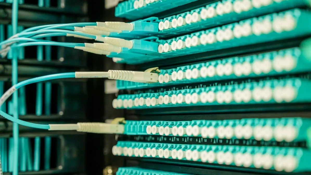
CWDM4 multiplexes four optical wavelengths inside the module so that the 100G interface uses a duplex LC connector and one single-mode fiber pair. That makes the module suitable for an installed duplex plant, subject to the route and host checks below.
That convenience does not make every “1310 nm” path suitable. Confirm connector condition, route loss, reach and the remote-end interface before treating a duplex route as approved.
Check FEC and Host Mode Before Buying
FEC behavior can depend on the host platform, port mode and selected 100G interface. Do not copy a setting from another project and assume that it applies to a new switch, line card, NIC or firmware release. In addition, the host port, software and module combination must be checked for the specific PMD before approval.
If two ports link only after an undocumented override, the project is not ready for volume approval.
For a broader compatible-optics review, the MikroTik and Cisco behavior guide demonstrates why host acceptance and optical fit must be reviewed separately.
Calculate the Exact Optical Path
For either interface, compare the complete path loss with the selected transmitter and receiver limits. Include connector loss, patch-panel loss, adapter loss and any passive element in the route. Apply the same optical-budget method to both options. In addition, measure or record the route length, fiber type and connector condition, because these values affect the loss total and the approval.
For PSM4, verify the continuity and loss of every used lane. For CWDM4, verify the duplex path and both installed strands.
The ISP/WISP backhaul optics guide provides the wider route, growth and operational context when this interface decision is part of a broader backhaul or aggregation plan.
A Pre-Order 100G Interface Record
- Device, line card or NIC, port and software at both ends
- Exact module identity proposed at each endpoint
- Required PMD and interoperability expectation
- FEC setting and port mode
- Connector type, fiber type, strand count and route length
- MPO polarity/lane map or duplex LC path map
- Measured loss and available Tx/Rx readings
- Breakout requirement and remote endpoint identities
- Temperature, monitoring and coding requirements
- Quantity, spares, sample plan and target deployment date
If the project contains uncertain host or cable-plant combinations, use sample-testing support to define an acceptance test before a larger order.
Frequently Asked Questions
Can PSM4 and CWDM4 connect directly to each other?
No direct interoperability should be assumed. They use different optical architectures and physical connectors, and the remote endpoint must use the same PMD as the local module.
Does PSM4 always support 4x25G breakout?
No. Confirm the exact module, host port, software, breakout mode and cable assembly. Parallel lanes do not guarantee breakout.
Is CWDM4 the same as a passive CWDM line-system channel?
No. CWDM4 is a defined multi-wavelength 100G interface. A passive CWDM MUX path must be checked by its own channel plan, passband and loss, and it should not be assumed to be a CWDM4 interface.
Which option uses fewer fiber strands?
CWDM4 normally uses a duplex pair, while PSM4 uses parallel transmit and receive fibers. The correct choice still depends on the installed plant, host and optical budget.
What evidence is needed for an interface review?
Provide both hosts, port modes, exact module references, FEC, fiber and connector map, route loss, breakout requirements and remote-end information.
Approve the Interface and the Cable Plant Together
Share the host platforms, intended 100G interface, MPO or LC path, FEC, route loss, breakout requirement and rollout plan. Axonode can help organize the interface decision and identify which host, cable or validation inputs remain open before the BOM is released.
Send your platform, distance and quantity to check options: https://www.axonode.net/contact-us