WISP Tower Optics Spares: What to Standardize Before a Failure
Build a practical WISP optics spare plan by standardizing host coding, reach, fiber type, BiDi direction, labels, storage and field replacement records.
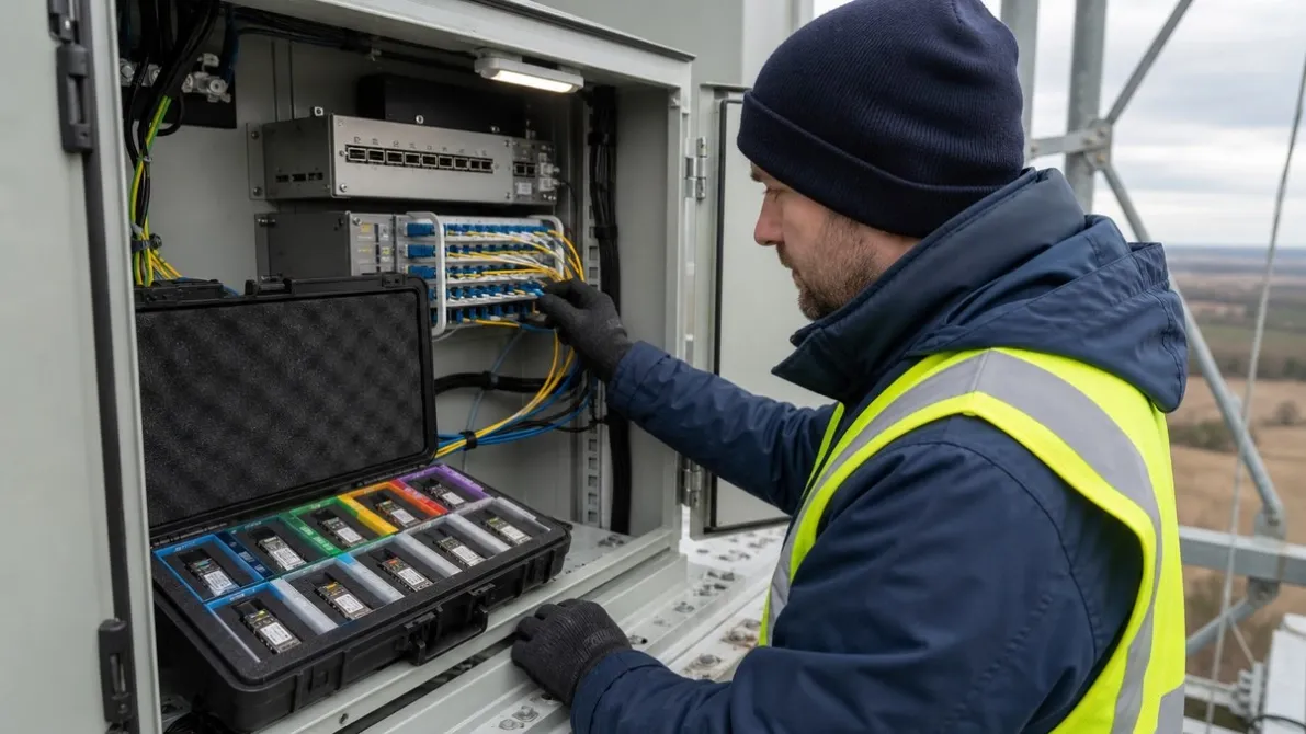
Operational objective: Build a small, controlled optics spare pool that restores real WISP links without tying up unnecessary inventory.
A spare optical transceiver is useful only when it matches the failed link. At a remote WISP site, “one spare SFP” is not a complete recovery plan. The technician may arrive with the wrong data rate, reach, fiber type, connector, host coding or BiDi direction—and the outage continues.
The goal is not to buy a large quantity of every optic. It is to create a small, controlled spare pool that covers the network’s real failure scenarios without tying up unnecessary cash.
This guide shows what WISP operators should standardize before a failure, how to build a site-to-spare matrix and what information must travel with every replacement module.
Why Generic Spare Stock Fails at Remote Sites
WISP networks often combine several generations of equipment. A core or aggregation location may use one switch family, while tower cabinets and customer-facing sites use different platforms. Links can also vary by speed, distance and fiber architecture.
That creates several ways for an apparently correct spare to be unusable:
- The form factor fits, but the data rate or port mode does not.
- The module has the right rate but the wrong reach or fiber type.
- The optic is coded for a different host platform.
- A BiDi module has the wrong transmit/receive direction.
- The connector does not match the installed patching.
- The host needs a particular software version, FEC mode or port configuration.
- The module is physically damaged, contaminated or no longer traceable.
The useful unit of planning is therefore not the product name. It is the site–port–link requirement.
Start With a Site-to-Spare Matrix
Create one row for every operationally important optical link. If both endpoints are under your control, record both ends separately.
| Field | What to record |
|---|---|
| Site and link ID | A stable identifier that field and NOC teams both recognize |
| Endpoint A | Device vendor, model, line card and port |
| Endpoint B | Device vendor, model, line card and port |
| Software | Current software or firmware version at each endpoint |
| Data rate | 1G, 10G, 25G, 40G, 100G or other active rate |
| Port mode | Native rate, breakout mode, lane configuration and FEC when relevant |
| Fiber | Single-mode or multimode; one strand or duplex pair |
| Connector | LC simplex, LC duplex or the exact installed interface |
| Route | Distance, measured loss and major passive elements |
| Installed optic | Exact part number, coding profile and serial number |
| Spare mapping | Approved replacement part and storage location |
| Criticality | Impact of failure and acceptable restoration time |
This matrix exposes duplicate requirements that can share a spare and exceptions that need their own module. It also prevents a technician from selecting a replacement from memory during an outage.
Standardize the Compatibility Identity
Two optics with the same speed and reach can behave differently in a host. Before approving a spare, confirm:
- Host vendor and exact device model.
- Line card, network interface card or sub-module when applicable.
- Software or firmware version.
- Port type, speed and lane configuration.
- Required vendor identification or coding profile.
- FEC requirements for higher-rate links.
- Digital optical monitoring expectations.
- Any support-policy limitation associated with third-party optics.
Coding acceptance is only one layer. A host reading the module identity does not prove that the optical link, FEC state and monitoring behavior are correct.
Use the optical transceiver compatibility check before adding a replacement optic to the approved spare pool.
Standardize the Optical Requirement
Do not group optics by color, label or form factor. Record the fields that determine whether the replacement fits the link.
Data Rate and Port Mode
An SFP-family cage does not by itself establish the operating rate. Record the active port configuration and whether the link uses auto-negotiation, a forced speed, breakout or a specific forward error correction mode.
Fiber and Connector
Separate multimode and single-mode requirements. Also separate simplex and duplex connector plans. A duplex-LC spare cannot directly replace a simplex-LC BiDi module simply because both are SFP+ optics.
Reach and Optical Power Window
Use the exact module specification and route loss. A longer nominal reach is not automatically a safer universal spare: on a short, low-loss path, receiver overload may need to be checked.
Passive Components
If the route includes patch panels, splitters, filters or mux/demux units, record them. Their insertion loss and wavelength behavior are part of the replacement decision.
Treat BiDi Spares as Directional Pairs
Single-fiber BiDi links require complementary transmit and receive wavelengths. If one end transmits at wavelength A and receives at wavelength B, the far end must transmit at B and receive at A.
This creates a common spare-stock failure: the team owns several modules with the correct speed and reach, but all are the same direction.
For every BiDi family:
- Record both TX/RX wavelength directions.
- Assign clear A-end and B-end identifiers.
- Store the pair together or use visibly different compartments.
- Count spare coverage by usable pairs, not total pieces.
- Confirm the direction before leaving for the site.
- Keep directional labels readable without opening antistatic packaging.
See the BiDi optical transceiver collection when mapping the appropriate product family. The final spare still needs pair-level verification.
Decide Where Each Spare Should Live
Centralized inventory and site-level inventory solve different problems.
| Storage model | Best fit | Main risk |
|---|---|---|
| Central spare pool | Several sites share common optics and delivery time is acceptable | Travel or dispatch delay during an outage |
| Regional maintenance point | A cluster of remote sites needs faster access | Inventory can become fragmented without one owner |
| On-site critical spare | A high-impact site is difficult to reach or has a strict restoration target | More capital and environmental exposure at each site |
| Technician field kit | Frequently used, well-standardized replacements | Poor tracking can turn the kit into unknown inventory |
Choose the location from site criticality, travel time, access conditions and the network’s restoration objective. Do not place expensive optics at every tower simply because a generic rule recommends it.
For broader link and topology planning, review the ISP/WISP backhaul optics solution.
Build a Small Approved Spare BOM
Start with installed demand rather than a supplier catalogue.
Step 1: Group Identical Requirements
Group links only when their rate, form factor, fiber architecture, reach class, coding requirements and host behavior are genuinely interchangeable.
Step 2: Separate Exceptions
Create dedicated lines for:
- BiDi A and B directions.
- Uncommon reach classes.
- Different host coding profiles.
- Higher-power or high-temperature requirements.
- Breakout, DAC or AOC assemblies with fixed endpoint behavior.
- Links involving passive WDM components.
Step 3: Assign Criticality
Classify each link by service impact, redundancy and replacement access. A protected link with a nearby maintenance center does not require the same spare placement as an unprotected remote tower.
Step 4: Set Quantity From Risk
Use the number of installed units, observed failure history, replenishment time, site access and acceptable outage duration. Do not use one universal percentage for every module family.
Step 5: Approve the Replacement Evidence
Record whether the spare has only passed a specification review, has been coded for the host, has completed controlled validation or has already been used successfully in the same environment. Do not collapse these evidence levels into “compatible.”
Label for a Technician Working Under Pressure
The package should answer the replacement questions without requiring an internet connection.
Include:
- Internal spare ID.
- Data rate and form factor.
- Optical family and reach.
- Fiber and connector type.
- Host coding profile.
- BiDi direction and TX/RX wavelengths where applicable.
- Approved site or platform group.
- Validation status and date.
- Storage owner and check-out record.
Avoid labels such as “Cisco SFP” or “10G long range.” They omit the exact platform, optical requirement and evidence level.
Prepare the Field Replacement Kit
The optic alone is not a complete field kit. Depending on the site, the approved kit may also include:
- Clean antistatic packaging.
- LC cleaning tools and inspection supplies.
- Correct patch cords or adapters.
- A printed or offline link record.
- A method to capture alarms and digital diagnostics.
- A safe container for the removed module.
- Escalation details for the network operations team.
Connector inspection and cleaning should occur before the team concludes that the installed optic has failed. Replacing a module does not repair a contaminated connector or damaged patch cord.
Use a Controlled Replacement Workflow
- Confirm the affected link and both endpoint records.
- Capture the original alarm, port state and diagnostic readings when available.
- Check patching, connector cleanliness and obvious physical damage.
- Verify the spare’s rate, reach, coding and BiDi direction.
- Replace one component at a time.
- Confirm link state, FEC, alarms and received power after replacement.
- Observe the link under representative traffic.
- Record the removed module, installed spare and outcome.
- Replenish the approved spare position only after confirming the correct identity.
This workflow helps distinguish a failed optic from a fiber fault, remote-end problem, port configuration issue or unsupported host condition.
Review the Spare Pool Regularly
Spare stock becomes unreliable when the network changes but the inventory does not.
Review the matrix after:
- A switch, router or line-card replacement.
- A software upgrade that changes transceiver support.
- A link-speed or FEC change.
- A migration between duplex and single-fiber optics.
- A new wavelength or WDM plan.
- An outage in which the planned spare did not fit.
- A long storage period or evidence of poor environmental conditions.
Retire obsolete mappings carefully. A module can remain physically functional while no longer matching any active site.
Final WISP Optics Spare Checklist
- Every critical link has a site–port–link record.
- Host model, software and coding profile are documented.
- Rate, port mode and FEC requirements are recorded.
- Fiber type, strand count and connector are confirmed.
- Reach is tied to the route loss, not the label alone.
- BiDi A/B directions are stocked as usable pairs.
- Spare locations reflect travel time and site criticality.
- Labels can be understood offline by field staff.
- Validation evidence is recorded for each approved replacement.
- Check-out, failure and replenishment records have an owner.
FAQ
How many spare optical transceivers should a WISP keep?
There is no universal quantity. Base the number on installed units, link criticality, redundancy, site access, observed failure history and supplier replenishment time. Standardize common requirements first so fewer spare families can cover more sites safely.
Can one long-reach optic serve as the spare for shorter links?
Not automatically. The host, fiber, wavelength and connector must match, and a short low-loss route may create receiver-overload risk. Approve each substitution against the exact module power limits and route loss.
Should BiDi spares be counted by pieces or pairs?
Plan operational coverage by complementary pairs. A stock count of four identical A-direction modules does not restore a link that needs a B-direction replacement.
Can the same spare work in switches from different vendors?
Only when the exact platforms, software and coding behavior have been reviewed or validated. Form factor and optical specification alone do not prove multi-vendor compatibility.
Should every tower keep its own spare optics?
Not necessarily. Use on-site stock for sites where access time and service impact justify it. Common optics may be more efficiently controlled from a central or regional maintenance point.
How should stored optics be labeled?
Include rate, form factor, reach, fiber and connector type, host coding, BiDi direction when applicable, approved site group and validation status. Keep the label readable without removing the module from protective packaging.
What should be checked after installing a spare?
Confirm link state, alarms, FEC status, digital diagnostic readings and received power where supported. Observe representative traffic and record whether the replacement resolved the original fault.
Need Help Standardizing a WISP Optics Spare BOM?
Send Axonode your site list, equipment models, active link rates, route distances, fiber types and current optic part numbers. We can help organize a compact replacement BOM, identify BiDi directional pairs and flag the compatibility or validation gaps that should be resolved before the modules are placed in field stock.