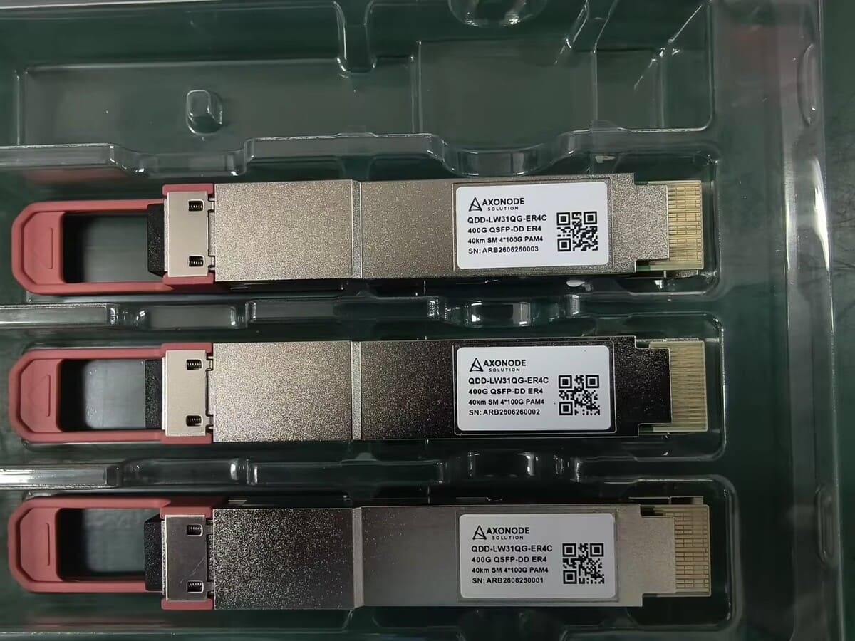
Can Long-Reach Optical Transceivers Overload a Short Fiber Link?
Learn how to check receiver overload when long-reach optical transceivers are used on a short, low-loss fiber link and when attenuation may be required.
Yes—a long-reach transceiver can overload a receiver on a very short, low-loss path.
Approve the connection from the exact transmitter and receiver limits, not from the reach label alone.
Before connecting ER, ZR or another high-power interface across a short patch, compare the worst-case received power with the maximum receiver input or overload limit at both ends. If the operating window is unclear, hold the test until the module specifications and path loss are verified.
Why Reach Labels Do Not Approve a Short Link
LR, ER and ZR describe interface classes or market reach categories. They do not tell you whether a specific pair is safe and stable on a specific cable plant.
| Boundary | Why it matters |
|---|---|
| Maximum transmitter output | The highest power that may be launched into the path. |
| Minimum transmitter output | A boundary used in the low-power review. |
| Receiver sensitivity | The applicable low-power receive boundary. |
| Maximum receiver input / overload | The high-power boundary for the receiver. |
Do not substitute a similar module's data. Part number, wavelength, interface, temperature grade and implementation may change the relevant limits.
The Short-Link Overload Check
Compare the result with the receiver's specified maximum input or overload value. Include applicable measurement uncertainty and approved headroom. A result too close to the boundary is not a defensible approval.
High-power check
Use maximum Tx and minimum path loss to test the overload boundary.
Low-power check
Use the applicable minimum Tx, maximum route loss, penalties and margin.
A complete design remains inside both boundaries. Planning from maximum cable loss alone can hide overload risk on a clean, short route.
Information to Collect Before Connecting the Modules
| Check | Record |
|---|---|
| Endpoints | Host, line card or NIC, port, configured speed and software when relevant |
| Module identity | Exact part number, wavelength, connector and coding at both ends |
| Optical limits | Minimum/maximum Tx, sensitivity and maximum receiver input |
| Fiber path | Fiber type, actual length, patching, splices and passive devices |
| Evidence | Minimum/maximum loss, suitable measurements and monitoring accuracy |
| Acceptance plan | Power limits, alarms, error counters, test duration and rollback |
For single-fiber BiDi transceivers, verify complementary Tx/Rx wavelengths and calculate both directions separately.
When an Optical Attenuator May Be Appropriate
An attenuator may be appropriate when the verified high-power condition would otherwise exceed the receiver's approved operating range.
- Calculate maximum received power without attenuation.
- Determine the minimum attenuation needed below the approved high-power boundary.
- Recalculate the low-power condition with attenuation included.
- Confirm connector, polish, wavelength range, power handling and location.
- Measure the installed result and record the baseline.
Placement, BiDi and WDM Considerations
- •Protect the receiver in the relevant direction without compromising the opposite path.
- •For BiDi, verify attenuator behavior across both wavelengths on the shared fiber.
- •For WDM, confirm the wavelength range and actual channel path.
- •Label the value, direction and protected receiver in the link diagram and BOM.
What DOM/DDM Can Tell You
Digital optical monitoring can show module-reported Tx power, Rx power, temperature and alarms when supported. It is useful for seeing whether the operating point appears near a limit and for recording a baseline.
DOM/DDM does not replace exact specifications, a suitable optical power measurement or a complete compatibility review. Reported values may use internal or external calibration and have stated accuracy limits. Read what DOM/DDM can and cannot verify.
Symptoms Are Not Proof of Receiver Overload
Errors, unstable links or degraded performance are not specific to overload. Dirty connectors, incorrect wavelength pairing, host restrictions, FEC mismatch and fiber faults can look similar.
- Stop repeated plug-and-try testing if the power window is unknown.
- Verify module identity and optical limits.
- Inspect and clean interfaces.
- Measure path and receive power with suitable equipment.
- Review host status, alarms, FEC and counters.
- Add only verified attenuation.
- Repeat the acceptance test and save results.
If host acceptance is uncertain, use the optical transceiver compatibility review checklist.
Decision Table
| Condition | Next step |
|---|---|
| Rx below maximum with clear headroom | Continue to controlled validation and verify the low-power boundary. |
| Rx approaches or exceeds maximum | Select and validate suitable attenuation before production connection. |
| Limits or path loss unknown | Hold the test and obtain authoritative specifications or measurements. |
| Power in range but errors remain | Investigate compatibility, FEC, cleanliness, pairing and fiber condition. |
The 10G BiDi SFP+ 40km deployment guide shows a related review of pairing, power, overload and host compatibility.
Final Short-Link Checklist
- ✓Exact module identities and optical limits confirmed.
- ✓Maximum Tx compared with minimum path loss in both directions.
- ✓Low-power boundary recalculated with proposed attenuation.
- ✓BiDi pairing, connector, wavelength and monitoring limits checked.
- ✓Installed power, alarms, counters and attenuator location recorded.
Frequently Asked Questions
Can a long-reach optic damage a receiver on a short link?
Excessive input can put the receiver outside its specified range. Do not assume permanent damage or safety; compare exact limits before connecting.
Do all ER or ZR transceivers need attenuators?
No. The answer depends on exact transmitter output, receiver maximum input and real path loss.
Can I select an attenuator from distance?
No. Select attenuation from the verified optical window and confirm the installed result by measurement.
Does a high DOM Rx reading prove overload?
It is useful evidence, but compare it with the exact receiver limit and monitoring accuracy.
Why can errors remain when Rx power looks normal?
Power is one layer. Coding, host restrictions, FEC, wavelength pairing, cleanliness and fiber faults may also cause errors.
Need a Short-Link Power Review?
Share the endpoint equipment, module part numbers, Tx/Rx limits, fiber length, passive components and available measurements. Axonode can help organize the optical-window check before the optics and attenuator BOM is approved.
Request a short-link optics review