
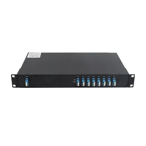
8-Channel 100GHz DWDM Mux Demux, C21–C28, Dual Fiber, LC/UPC
Passive 8-channel 100GHz DWDM mux/demux for ITU C21–C28, dual-fiber LC/UPC links, with an Express port for later channel-plan expansion.
PASSIVE 100GHz C-BAND MULTIPLEXING
8 channels · ITU C21–C28 · Dual fiber · LC/UPC · Express port
Combine eight fixed DWDM channels onto one transmit fiber and separate them on the receive fiber. Lock the exact channel plan, endpoint wavelengths and route loss before quotation.
Channel plan at a glance
The Express port is reserved for future expansion or a separately defined pass-through band. Its exact use must be stated in the optical design.
Dual-fiber direction
One common fiber carries the multiplexed transmit direction; the other carries the return direction.
Passive device
No active wavelength conversion occurs. Endpoint transceivers must already use the assigned ITU channels.
Typical deployment
Metro, access, data-center interconnect or dark-fiber capacity expansion using fixed C-band optics.
Reference optical specifications
| Parameter | Value |
|---|---|
| Channels | 8 channels, ITU C21–C28 |
| Channel spacing | 100GHz |
| Fiber topology / connector | Dual fiber / LC/UPC |
| Expansion interface | Express port |
| Channel insertion loss | ≤ 2.4dB |
| Adjacent / non-adjacent isolation | ≥ 30dB / ≥ 40dB |
| Channel passband / ripple | Minimum ±0.13nm / ≤ 0.5dB |
| Polarization dependent loss / PMD | ≤ 0.2dB / ≤ 0.2ps |
| Return loss / directivity | ≥ 45dB / ≥ 50dB |
| Maximum optical power | 500mW |
| Fiber | SMF-28e+ or confirmed equivalent single-mode fiber |
| Operating / storage temperature | -20 to +75°C / -40 to +85°C |
| Enclosure | LGX module or rack-mount format confirmed per order |
The table defines the selected reference configuration. Final port map, enclosure and measured optical limits must match the approved quotation and datasheet.
Build the end-to-end loss budget
Minimum transmit power, receiver sensitivity and overload on every C21–C28 channel.
Use the specified insertion loss at both ends of the link.
Fiber, connectors, splices, patch panels and any other passive elements.
Allowance for ageing, repairs, temperature and measurement uncertainty.
Frequently asked questions
Which channels are included?
The reference configuration contains eight 100GHz ITU channels, C21 through C28. Confirm the same plan for both mux/demux units and endpoint optics.
Is this CWDM or DWDM?
It is a 100GHz C-band DWDM device. Do not connect wide-spaced CWDM wavelengths to the C21–C28 channel ports.
Do both ends need matching mux/demux units?
A point-to-point dual-fiber system normally uses a matching channel plan at both ends. Confirm port direction and common-fiber mapping in the design.
What is the Express port for?
It can support planned expansion or a separately defined pass-through band. Its role must be agreed before production rather than left implicit.
How much mux/demux loss should be budgeted?
The selected reference limit is 2.4dB per channel for one unit. A full link normally includes a unit at each end plus fiber and connector losses.
Does the passive unit determine the transmission distance?
No. Endpoint optics, total passive loss, fiber attenuation, dispersion conditions and engineering margin determine the workable route.
Can a different eight-channel set be ordered?
Custom channel plans may be reviewed, but they are a separate configuration. State every required ITU channel and keep the two endpoints consistent.
What must be supplied with the RFQ?
Provide the channel list, endpoint optics, topology, common-fiber mapping, Express-port use, connector and enclosure, route loss, quantity and schedule.
Lock the C21–C28 channel plan before quotation
Send both-end channel assignments, transceiver wavelengths and power limits, dual-fiber direction, Express-port requirement, route length and loss, connector, enclosure, quantity and target date.
Request a DWDM path reviewProduct image is a user-approved representative type view. Final port labels and construction follow the approved quotation.