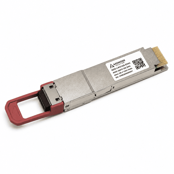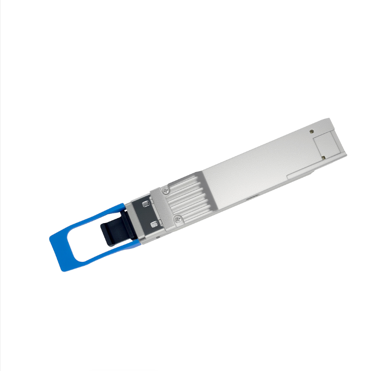
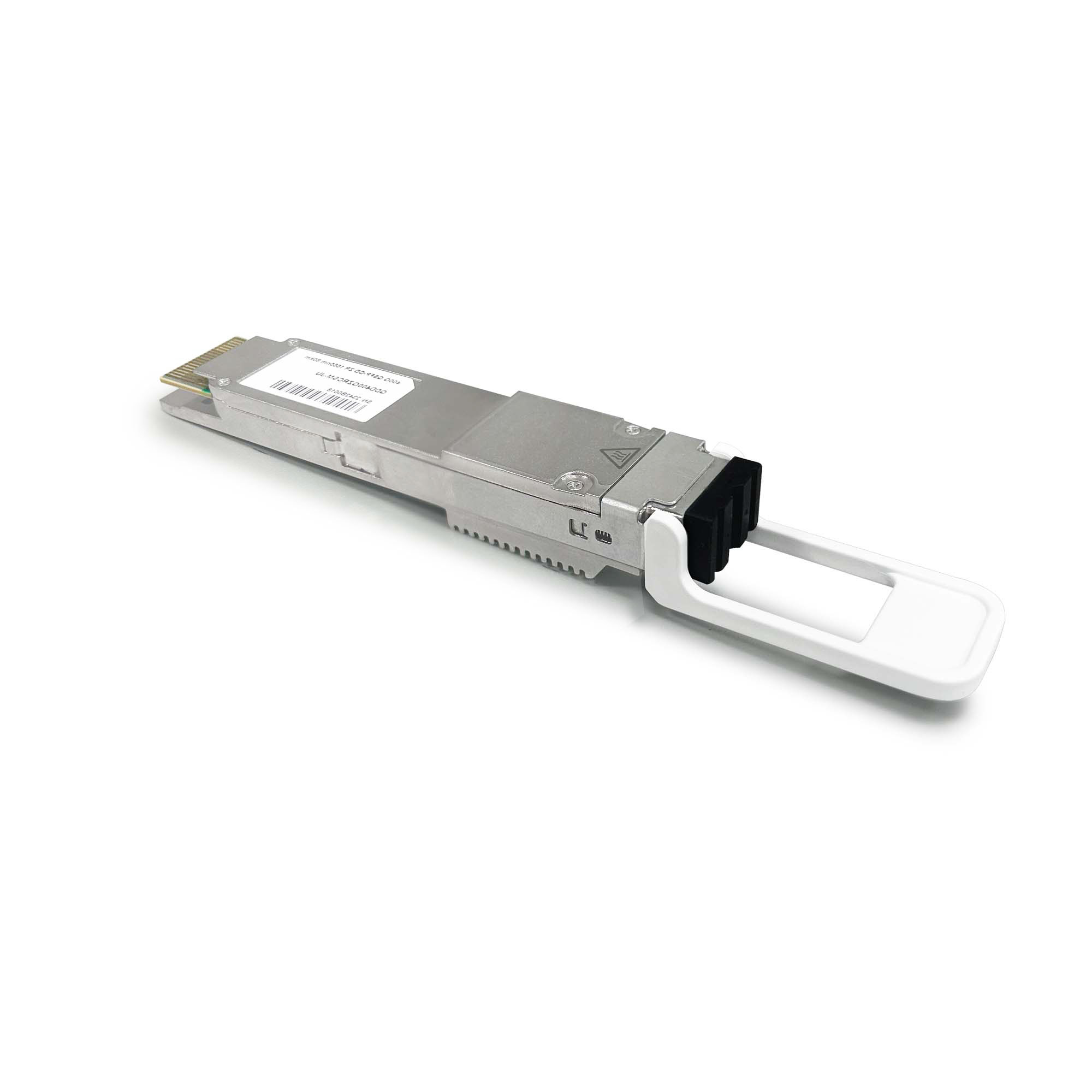
400G ZR Coherent QSFP-DD 80km Optical Transceiver
Tunable C-band 400G ZR coherent QSFP-DD for 400ZR Gray point-to-point links up to 80km over Duplex LC single-mode fiber. Verify route loss, OSNR, host power, cooling and matched application settings before ordering.
Specifications
- Warranty
- 3-Years
- Customization
- Free OEM labeling
- Delivery Time
- 48 hours dispatch
Confirm the 400ZR Gray link conditions first
The Axonode 400G ZR coherent QSFP-DD is configured for an unamplified point-to-point link of up to 80km in the verified 400ZR Gray operating profile. It uses a Duplex LC interface and integrated coherent DSP. Actual reach depends on end-to-end loss, optical signal-to-noise ratio (OSNR), host power and thermal capability, and matched application settings at both endpoints.
Coherent-capable QSFP-DD host
Confirm QSFP-DD Type 2B support, the required CMIS application mode, adequate power and cooling, and the intended host electrical mode.
Duplex LC / single-mode fiber
Use a clean Duplex LC single-mode path and include fiber, connector, splice and passive-component loss.
Validate the 80km route
The 80km figure is conditional. Check measured loss, OSNR, dispersion, channel settings and engineering margin.
400ZR Gray interface and optical specifications
Use the verified values below as the engineering baseline for the 80km configuration. Distance alone is not a link guarantee.
| Product type | Digital Coherent Optics (DCO) |
|---|---|
| Form factor | QSFP-DD MSA Type 2B |
| Operating profile | 400ZR Gray |
| Line rate | 400GbE |
| Modulation / FEC | DP-16QAM / CFEC |
| Symbol rate | 59.84375GBd ±20ppm |
| Reference reach | Up to 80km potential, unamplified, based on 0.25dB/km cabled-fiber attenuation |
| Fiber / connector | Single-mode fiber / Duplex LC |
| 400ZR Gray frequency | 193.7THz |
| Supported frequency range | 191.3–196.1THz, application-code dependent |
| Channel grid / tuning | 50GHz, 75GHz and 100GHz fixed grids; 3.125GHz flexible-grid granularity; 0.1GHz fine tuning |
| Transmit power, 400ZR Gray | +3dBm minimum, +4dBm typical, +5dBm maximum |
| Receiver sensitivity, 400ZR Gray | −20dBm with in-band OSNR ≥34dB |
| Transmit in-band OSNR | 38dB |
| Back-to-back OSNR tolerance | 26dB/0.1nm |
| CD / DGD tolerance | 2400ps/nm / 33ps |
| Host electrical interface | 1×400GAUI-8 or 4×100GAUI-2 host mapping |
| Supply voltage / current | 3.135–3.465V, 3.3V typical / 7.2A maximum |
| Power consumption | 22W typical, 22.5W maximum in 1×400GbE mode; up to 23W in 4×100GbE mode |
| Operating / storage temperature | 0 to +75°C / −40 to +85°C |
| Management and monitoring | I²C, CMIS/C-CMIS and digital diagnostics |
| Referenced standards | OIF-400ZR-02.0, OpenZR+ MSA 2.0, OIF-CMIS-05.2, OIF-C-CMIS-01.2, QSFP-DD Hardware Rev 6.3, IEEE 802.3-2018 and RoHS 2 |
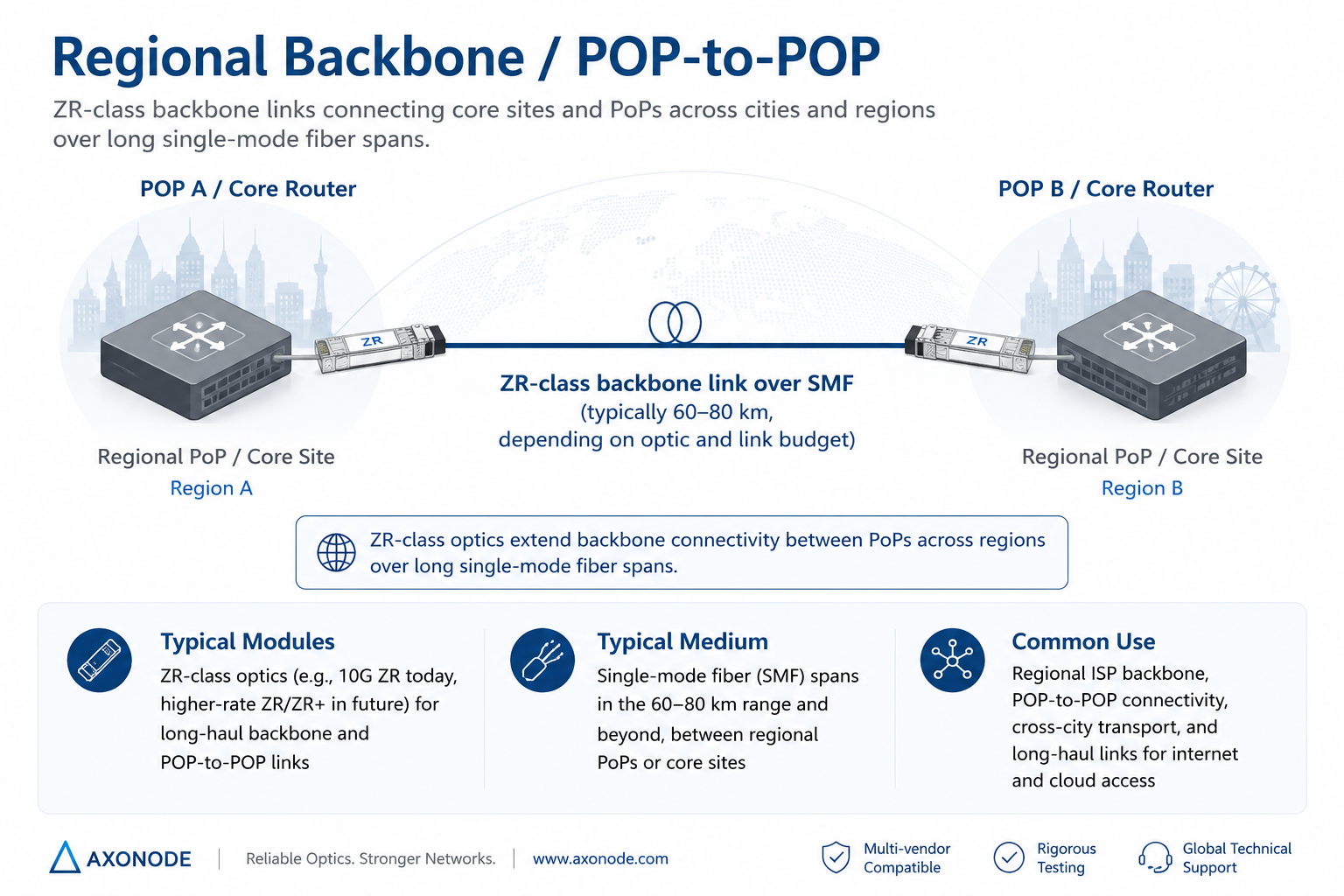
Typical 400G coherent 80km deployment
Use the 400ZR Gray profile for an engineered point-to-point metro or regional connection between coherent-capable QSFP-DD hosts. The diagram represents a ZR-class POP-to-POP link, not an unconditional reach guarantee.
Deployment considerations
Engineer the complete optical path
Measure the actual route and include fiber attenuation, patch panels, connectors, splices and passive optical components. The 80km value is a potential distance under the datasheet’s reference fiber-loss condition.
Match the coherent configuration
Both endpoints must use the same 400ZR application mode, frequency and CFEC settings. The 4×100G option is a host-side electrical mapping, not a physical optical breakout.
Check host power and cooling
A port may physically accept a QSFP-DD module without supporting its coherent application mode or power requirement. Confirm the line card, software release, CMIS application code, airflow direction and thermal capacity.
Validate filtered or amplified paths
For a mux, ROADM or EDFA route, review passband width, filter alignment, insertion loss, amplifier gain and noise contribution. Do not apply the direct-fiber 80km figure unchanged to an optical line system.
Compatibility
QSFP-DD mechanical fit alone does not establish compatibility. Confirm the exact host platform, line card, software release, CMIS application mode, power class, cooling capability and required coding before shipment. Standards alignment may support multi-vendor operation, but the selected line mode, FEC, frequency and management behavior still require validation.
Frequently Asked Questions
Does the 80km rating guarantee operation on every 80km fiber route?
No. The source describes a potential 80km reach using a 0.25dB/km cabled-fiber attenuation assumption. Actual operation depends on total loss, OSNR, dispersion, connectors, splices, passive components and engineering margin.
Does an 80km 400G coherent link require an EDFA?
Not for the reference unamplified 400ZR Gray application. If measured loss or another path condition exceeds the supported operating range, review the complete link before deciding whether amplification or a different design is appropriate.
Can this module be used on dark fiber and an optical line system?
Direct dark fiber is the reference 80km use case. A mux, ROADM or EDFA path may also be possible, but channel spacing, filter passband, insertion loss, amplifier gain and OSNR must be checked separately.
What must the host platform support?
The host must support QSFP-DD Type 2B, the required coherent CMIS application mode, adequate power and cooling, and the selected 1×400GAUI-8 or 4×100GAUI-2 electrical configuration. Confirm the exact line card and software release.
How should the optical frequency be selected?
Configure the same frequency and grid at both endpoints. The target 400ZR Gray profile uses 193.7THz; other supported tunable settings are application-code dependent.
Which modulation and FEC apply to the 80km configuration?
The target 400ZR Gray mode uses dual-polarization 16QAM and CFEC. Both endpoints must use matching line-mode, FEC and frequency settings.
Is an external dispersion-compensation module required?
Do not add one automatically. The specified 400ZR mode provides up to 2400ps/nm chromatic-dispersion tolerance, so compare the accumulated dispersion of the actual route with that limit first.
Can coherent modules from different vendors be used at opposite ends?
Potentially, but standards alignment alone does not guarantee every implementation will interoperate. Verify line mode, FEC, frequency, application code, host software and management behavior, followed by laboratory or field validation where required.
What should be recorded during commissioning?
Record the configured frequency, received power, OSNR where available, module temperature, power consumption, pre-FEC BER, corrected or uncorrected errors and active alarms.
Why might the host recognize the module while the optical link remains down?
Common causes include a mismatched CMIS application code, frequency, line mode or FEC; insufficient host power or cooling; excessive route loss; low OSNR; or a filtered channel that is not correctly aligned.
Downloads
The 400G coherent 80km technical file is available on request. Share the intended 400ZR mode, host platform, channel frequency and route conditions so the correct technical information and configuration can be supplied.
Request the 400G coherent 80km technical file
Validate your 400G coherent 80km link before ordering
Send the host and line-card model, software release, port application mode, actual route length, measured end-to-end loss, fiber topology, required frequency or grid, and details of any mux, ROADM or EDFA. Include the operating environment, quantity and required delivery date.