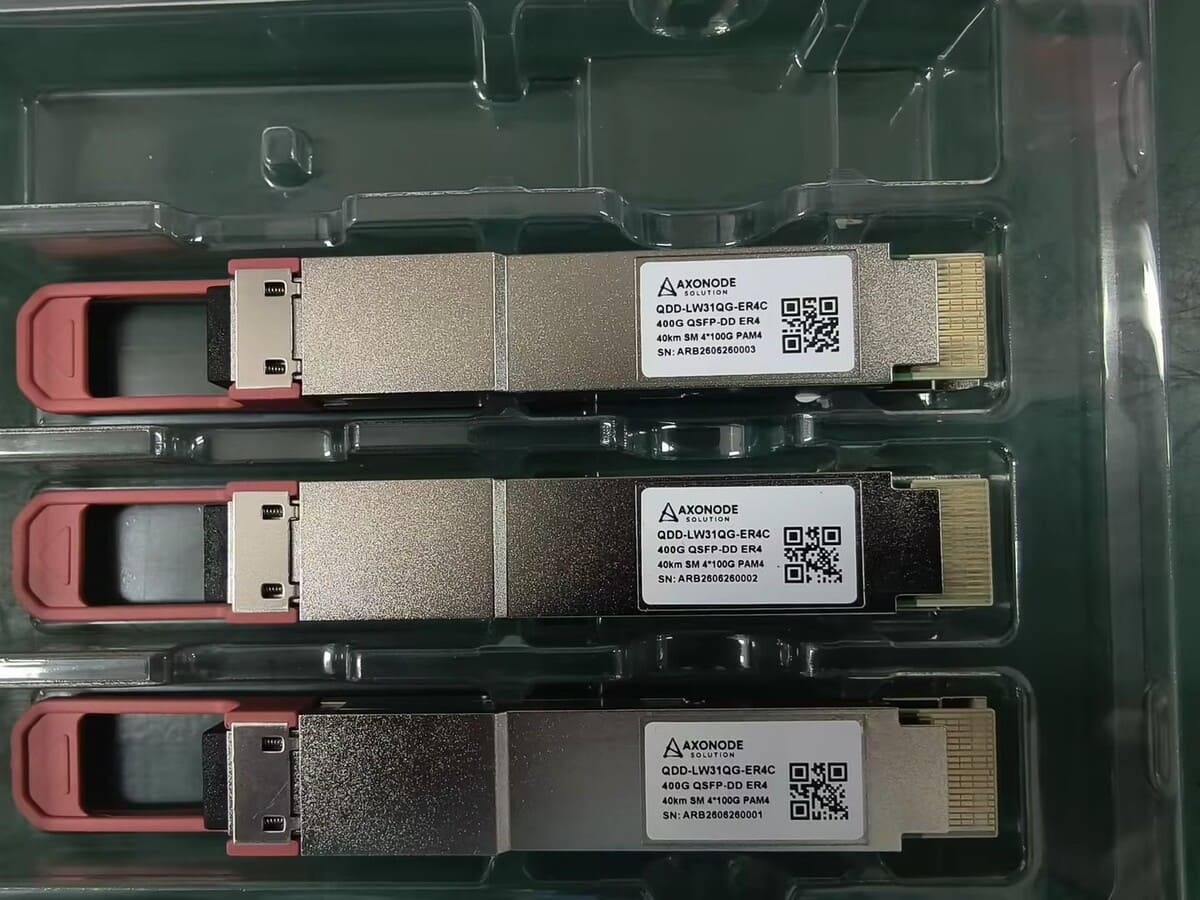
QSFP-DD or OSFP? A Host-First Form-Factor Checklist for 400G and 800G
Compare QSFP-DD and OSFP by host cage, rate, lane interface, cooling, power, connector, PMD, software, compatibility evidence and rollout needs.

QSFP-DD and OSFP are not two packaging choices that can be substituted after the optical specification is selected. The host cage, electrical interface, cooling design, power envelope, software and supported optical PMD determine which form factor and module can be used.
Start with the exact platform and port. Then select the optical interface, connector, reach and operating requirements inside the form factor that the host supports.
Confirm the Physical Host Interface
Record the device, line card, port, cage type and supported module families. QSFP-DD and OSFP are distinct form factors and are not physically interchangeable in the same cage without a platform-supported adapter strategy.
The QSFP-DD Multi Source Agreement defines a double-density eight-lane pluggable architecture in the QSFP family. The OSFP Multi Source Agreement defines its own pluggable form factor. These specifications describe mechanical and electrical frameworks; they do not certify a particular module for a particular switch.
| Host field | What to verify |
|---|---|
| Platform and card | Exact hardware revision where documented |
| Cage | QSFP-DD, OSFP, OSFP-RHS or another documented interface |
| Port rate | Supported aggregate rate and permitted operating modes |
| Electrical lanes | Lane count, signaling rate and host interface required by the module |
| Software | Minimum or supported network operating system release |
| Population rules | Port groups, power and thermal restrictions when documented |
Use the optical transceiver compatibility check to build the platform evidence package before requesting compatible high-speed optics.
Separate Form Factor, Data Rate and PMD
A form factor does not define the optical reach or fiber interface. Within one form factor, modules may implement different Ethernet PMDs, coherent interfaces, connector types and fiber counts.
Write the BOM identity in layers:
- Host cage and supported form factor
- Aggregate rate and host electrical interface
- Exact optical PMD or application
- Connector and fiber topology
- Reach, optical limits and FEC requirements
- Management, coding and software requirements
Do not shorten the request to “400G OSFP” or “800G QSFP-DD.” Those descriptions still leave the optical path and host behavior unresolved.
Review Cooling and Power as Platform Limits
High-speed pluggables can have materially different power and thermal requirements across module types. Use the exact module maximum power and the platform’s documented limits.
The OSFP MSA notes that the standard OSFP form factor includes an integrated heatsink, while OSFP-RHS uses a separate riding heatsink supplied by the host cooling design. This distinction matters when the BOM describes the visible module but the platform expects a different thermal arrangement.
QSFP-DD platforms also use defined cage, heat-sink and airflow solutions. Do not compare the form factors from one typical power number. Check the exact module and switch combination, airflow direction, ambient conditions and permitted port population.
| Thermal question | Why it belongs in the BOM |
|---|---|
| Maximum module power | Must remain within the supported port and system envelope |
| Integrated or riding heatsink | Must match the host mechanical and cooling design |
| Airflow direction | Affects the system’s documented thermal operation |
| Adjacent-port population | Some platforms define density limits for higher-power modules |
| Ambient range | Must cover the installed environment, not only the lab |
Match the Optical Interface and Connector
After the host form factor is fixed, select the exact optical interface for the route. Record single-mode or multimode fiber, duplex or parallel topology, connector type, fiber count, route length and measured loss where available.
For parallel optics, the patching system must match the interface’s fiber positions, connector gender and polarity. For duplex interfaces, the two endpoint PMDs and connector polish still have to match. For coherent pluggables, line-system, wavelength, management and operational requirements may introduce additional review.
The optical budget must use the exact module specifications and actual passive path. A form factor comparison cannot approve a fiber link.
Check Backward or Adapter Use Only When Documented
Some platforms support selected lower-rate modules or adapters, but support is not universal. A mechanical fit or available adapter does not prove the host supports the electrical mode, module power, software behavior or optical interface.
Record the adapter part, approved module family, supported rate and software evidence. Treat adapter-based operation as its own BOM identity and validation scope. Do not carry a successful result from one platform into another device without evidence.
If the project replaces an existing fleet, the optical transceiver upgrade checklist helps connect port audits, fiber readiness, staging and rollback.
Include Management and Coding Requirements
The module management interface and host implementation affect inventory, diagnostics, alarms, firmware interaction and configuration. Confirm the exact platform’s support for the module type and required management behavior.
Coding review remains host-specific. “QSFP-DD compatible” or “OSFP compatible” is not a complete requirement. Record vendor, platform, port, software, original part number and whether the evidence is based on documentation, supplier coding verification, controlled validation or scoped field evidence.
Do not claim full compatibility from module recognition or readable diagnostics alone.
Plan Validation at Realistic Port Density
A single module on an open bench does not represent every thermal and operational condition. Define a controlled validation that reflects the rollout risk.
Check the exact host, software, port mode, FEC, remote endpoint, fiber path and link behavior. For higher-power deployments, include the planned port population and cooling conditions when the platform documentation requires them. Record inventory, alarms, relevant error counters and optical readings where supported.
The validation scope should state what was tested and what remains an assumption. Production approval should not expand beyond that scope silently.
Final QSFP-DD or OSFP Checklist
- The exact host platform, card, port and cage are recorded.
- Form factor, aggregate rate and electrical lane interface are not confused.
- The optical PMD, connector, fiber topology and reach are explicit.
- Maximum power and platform thermal limits are checked.
- Integrated, riding or host heat-sink requirements are documented.
- FEC and software requirements are aligned at both endpoints.
- Adapter or lower-rate use has platform-specific evidence.
- Coding and management requirements are tied to the exact host.
- Sample, production and spare quantities are separated.
- Validation reflects the planned port density and deployment environment.
Frequently Asked Questions
Can a QSFP-DD module be inserted into an OSFP port?
They are different form factors. Do not assume direct physical or electrical interchangeability. Use only a platform-documented adapter and module combination when one is supported.
Does QSFP-DD always mean 400G and OSFP always mean 800G?
No. Form factor and aggregate rate are separate identity fields. Confirm the exact module, host electrical interface and supported operating mode.
Is OSFP always cooler because it is larger?
Do not approve a design from form-factor size alone. Compare the exact module power with the host cooling solution, heatsink arrangement, airflow and population rules.
Can the same optical PMD be available in both form factors?
Some PMDs may be implemented in more than one form factor, but each exact module still requires host, connector, optical, FEC and management review.
Is readable CMIS or diagnostic data proof of compatibility?
No. Management visibility is useful evidence, but it does not prove that the host supports the complete interface, configuration and deployment context.
What should be sent for a QSFP-DD or OSFP review?
Send both hosts, cards and ports, software versions, cage types, required rates and PMDs, fiber and connector details, route length, FEC, power and thermal constraints, quantities and validation plan.
Choose the Module Inside the Host’s Real Limits
Share the exact platforms, ports, software, required rates and PMDs, connector and fiber path, thermal constraints, quantities and rollout plan. Axonode can help organize a form-factor and optics BOM and identify what still needs host or link validation.
Review a high-speed optics BOM